42
OPERATION
5.2
ACCESS CODES
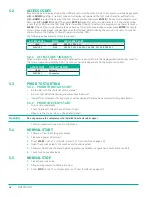
Access to page list displays higher than P00 are restricted by access code. To access menu mode pages press
UP
and
DOWN
together, an access code entry display is shown and the first code character will flash. Use
UP
or
DOWN
to adjust the value of the first code character then press
ENTER
. The next code character will
flash; use
UP
or
DOWN
to adjust then press
ENTER
. Repeat for all four code characters. If the code number
is less than 1000, then the first code character will be 0 (zero). To return to a previous code character press
CLEAR
. When all four code characters have been set to an authorized code number press
ENTER
. Access to
certain menu mode pages is dependent on authority level determined by the access code used. An invalid
code will return the display to normal operational mode, P00.
The following pages and access levels are used:
ACCESS LEVEL
CODE
AVAILAbLE PAGES
USER
0009
P00, P01, P02, P11
SERVICE 1
0100
P00, P01, P02, P03, P04, P05, P06, P07, P08, P09, P11
5.2.1 ACCESS CODE TIMEOUTS
When in menu mode, if no key activity is detected for a period of time the display will automatically reset to
the normal operational display, P00. The timeout period is dependent on the access code used.
ACCESS CODE
TIME OUT PERIOD
USER
1 minute
SERVICE 1
10 minutes
5.3
PRIOR TO STARTING
5.3.1 PRIOR TO INITIAL START
»
be familiar with the contents of this manual.
»
be sure that all installation requirements have been met.
»
Inspect the compressor for any signs of visible damage that may have occurred during installation.
5.3.2 PRIOR TO EVERY START
»
Drain sump condensate.
»
Check fluid levels. Check that oil fill cap is tight.
»
Make sure the starter door is closed and latched.
WARNING!
Do not power up the compressor starter with the starter door open!
»
Check all pressure connections for tightness.
5.4
NORMAL START
1.
2.
Close main power disconnect.
3.
Press
START
on the T1 controller (refer to
).
4.
Open the service valve to the plant air distribution system.
5.
Allow machine to reach normal operating pressure and observe operation of automatic controls.
6.
Check for any possible leaks.
5.5
NORMAL STOP
1.
Close the service valve.
2.
Allow sump pressure to fall to 40–45 psi.
3.
Press
STOP
on the T1 controller (refer to
Содержание UD Series
Страница 6: ...vi About This Manual ...
Страница 12: ...4 Introduction ...
Страница 24: ...16 Specifications 2 2 DIMENSIONS OPEN AIR COOLED 230V Figure 2 1 GA 30 40 50UD AC VFD 230V R00 ...
Страница 25: ...17 Specifications 2 3 DIMENSIONS OPEN AIR COOLED 460V Figure 2 2 GA 30 40 50UD AC MPC VFD OPEN 460V R00 ...
Страница 26: ...18 Specifications 2 4 DIMENSIONS ENCLOSED AIR COOLED 460V Figure 2 3 GA 40 50 60UDAC ENC S1 R00 ...
Страница 27: ...19 Specifications 2 5 DIMENSIONS ENCLOSED HEAVY DUTY INLET OPTION 460V Figure 2 4 GA 40 50 60UDAC VFD ENC R00 ...
Страница 28: ...20 Specifications 2 6 DIMENSIONS ENCLOSED AIR COOLED HD INLET NO BUSSEL Figure 2 5 GA 60UDAC ENC VFD NB R00 ...
Страница 29: ...21 Specifications 2 7 PIPING AND INSTRUMENTATION AIR COOLED Figure 2 6 P I 15 40D AC MPC VFD R02 ...
Страница 42: ...34 Component Description ...
Страница 52: ...44 Operation ...
Страница 66: ...58 Troubleshooting ...
Страница 74: ...66 Parts Catalog 8 5 COMPRESSOR FRAME AND DRIVE ASSEMBLY Figure 8 1 AS801 25UD 50UD VFD R00 ...
Страница 76: ...68 Parts Catalog 8 6 CONTROL ASSEMBLY OPEN Figure 8 2 1072190415 609 R00 ...
Страница 78: ...70 Parts Catalog 8 7 STARTER ASSEMBLY ENCLOSED Figure 8 3 AS802 405060 PANEL R03 ...
Страница 80: ...72 Parts Catalog 8 8 AIR INLET ASSEMBLY 15 30HP 13 12 11 13 12 4 5 2 3 14 1 Figure 8 4 AS805 030D7H TE R00 ...
Страница 94: ...86 Parts Catalog 8 15 COOLING ASSEMBLY AIR COOLED Figure 8 11 AS804 50UDAC INLINE R00 ...
Страница 100: ...NOTES ...
Страница 101: ...NOTES ...


