17
CoMPoNENT DESCRIPTIoN
3.5
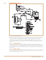
LUBRICATION SYSTEM
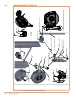
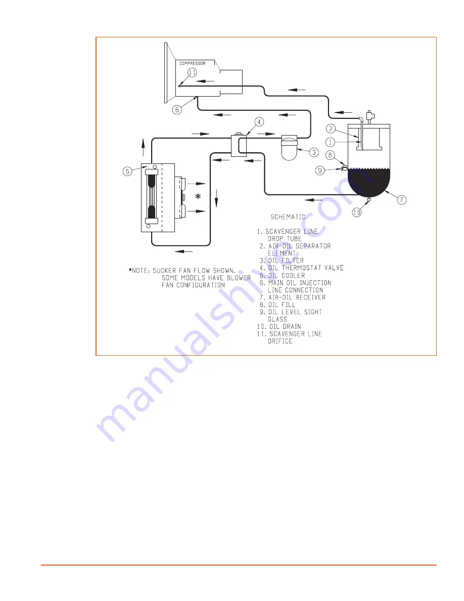
Figure 3-2.
DIAGRAM, OIL PIPING 185-375 (REV 00)
Oil from the compressor oil sump at compressor discharge pressure is directed through the cooling system
and oil filter to a lower pressure region of the compressor stator. At the same time, oil is directed to the
bearings and shaft seal of the compressor. The oil-laden air is then discharged back into the sump.
The compressor cooling system consists of an oil cooler mounted adjacent to the engine radiator. Cooling
air is pushed through the cooler by the engine fan while oil is circulated through it by the receiver/sump
pressure.
3.5.1
OIL RETURN LINE
The oil that is removed by the air/oil separator gravitates to the bottom of the air/oil separator and is
returned through an orifice in the oil return scavenger line assembly. The assembly consists of a pickup tube,
return line hose, a line strainer and a sight glass/orifice. Flow can be witnessed through the sight glass. Flow
is generated via differential pressure between the high pressure sump tank and the lower pressure region of
the compressor.
3.5.2 THERMAL VALVE
The thermal valve is the center of the compressor temperature regulating system. oil circulates through the
valve until the oil temperature reaches 140°F at which time the thermostat closes to force the oil through
the cooler before returning to the air end.
Содержание D260UJD4PTOW
Страница 4: ......
Страница 6: ...vi About This Manual ...
Страница 14: ...6 Safety ...
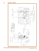
Страница 21: ...13 Specifications 2 6 PTO SAE A DRIVE Figure 2 5 Power Take Off Auxiliary Drive Specs ...
Страница 22: ...14 Specifications ...
Страница 32: ...24 Component Description ...
Страница 44: ...36 Installation and Operation ...
Страница 58: ...50 Troubleshooting ...
Страница 125: ...117 Parts Catalog ...
Страница 134: ...NOTES ...
Страница 135: ...NOTES ...

