


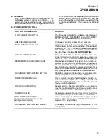


Section 5
OPERATION
14
5.3 INITIAL START--UP PROCEDURE
The following procedure should be used to make the
initial start--up of the compressor.
1. Read the preceding pages of this manual thor-
oughly.
2. Jog motor to check for correct rotation of fan (re-
) .
3. Be sure that all preparations and checks de-
scribed in the Installation Section have been
made.
4. Open the shut--off valve to the service line.
5. Start the compressor by turning the selector
switch to “manual” or “automatic”.
6. Check for possible leaks in piping.
7. Slowly close the shut--off valve and check that the
pressure switch is set correctly. If set correctly,
the compressor will unload at nameplate pres-
sure. If adjustments are necessary, see Control
System Adjustment in Section 6, Maintenance of
this manual.
8. Observe the operating temperature. If the operat-
ing temperature exceeds 200
q
F (93
q
C), the cool-
ing system and installation environment should
be checked.
9. Open shut--off valve to the service line.
10. Reinspect the compressor for temperature and
leaks the following day.
5.4 SUBSEQUENT START--UP PROCEDURE
On subsequent start--ups, check that the proper lev-
el is visible in the fluid level sight glass and simply
turn selector switch to desired control. When the
compressor is running, observe the instrumenta-
tion.
5.5 SHUTDOWN PROCEDURE
To shut the compressor down, simply turn selector
switch to OFF/RESET position.
Содержание ES-6 series
Страница 6: ...NOTES...
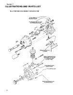
Страница 30: ...Section 7 ILLUSTRATIONS AND PARTS LIST 24 ES 6 COMPRESSOR ASSEMBLY EXPLODED VIEW 5 5 AND 7 5KW...
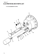
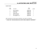
Страница 32: ...Section 7 ILLUSTRATIONS AND PARTS LIST 26 7 3 FLUID MANAGEMENT SYSTEM...
Страница 34: ...Section 7 ILLUSTRATIONS AND PARTS LIST 28 7 4 INLET FILTER...
Страница 36: ...Section 7 ILLUSTRATIONS AND PARTS LIST 30 7 5 SEAL AND DRIVE GEAR...
Страница 38: ...Section 7 ILLUSTRATIONS AND PARTS LIST 32 7 6 MOTOR HOUSING AND PARTS 7 5 10HP 5 5 7 5KW ONLY...
Страница 40: ...Section 7 ILLUSTRATIONS AND PARTS LIST 34 7 7 COMPRESSOR COOLER SYSTEM 7 5 10HP 5 5 7 5KW COOLER...
Страница 42: ...Section 7 ILLUSTRATIONS AND PARTS LIST 36 7 8 COMPRESSOR SYSTEM...
Страница 44: ...Section 7 ILLUSTRATIONS AND PARTS LIST 38 7 9 INLET CONTROL...
Страница 46: ...Section 7 ILLUSTRATIONS AND PARTS LIST 40 7 10 CONTROL BOX...
Страница 48: ...Section 7 ILLUSTRATIONS AND PARTS LIST 42 7 10 CONTROL BOX...
Страница 50: ...Section 7 ILLUSTRATIONS AND PARTS LIST 44 7 11 CANOPY AND PARTS 1 2 3 4 5 6 7 8 9 10 11 12 13 14 15 16 17 18...
Страница 52: ...Section 7 ILLUSTRATIONS AND PARTS LIST 46 7 12 FRAME CANOPY AND PARTS...
Страница 56: ...Section 7 ILLUSTRATIONS AND PARTS LIST 50 7 14 WYE DELTA ELECTRIC BOX ES 6...
Страница 58: ...Section 7 ILLUSTRATIONS AND PARTS LIST 52 7 15 DECAL GROUP 7 8 9 11 12...
Страница 60: ...Section 7 ILLUSTRATIONS AND PARTS LIST 54 7 15 DECAL GROUP 13...
Страница 62: ...Section 7 ILLUSTRATIONS AND PARTS LIST 56 7 16 WIRING DIAGRAM SINGLE PHASE 60Hz...
Страница 63: ...Section 7 ILLUSTRATIONS AND PARTS LIST 57 7 17 WIRING DIAGRAM THREE PHASE 60Hz...
Страница 64: ...Section 7 ILLUSTRATIONS AND PARTS LIST 58 7 18 WIRING DIAGRAM 50 Hz...
Страница 65: ...Section 7 ILLUSTRATIONS AND PARTS LIST 59 7 19 WIRING DIAGRAM 50 Hz WYE DELTA...
Страница 66: ...NOTES...
Страница 67: ...NOTES...


