background image

AIR CARE SEMINAR

TRAINING

Sullair Air Care Seminars are courses that provide hands-on instruction in the proper operation, maintenance
and service of Sullair equipment. Individual seminars on Industrial compressors and compressor electrical
systems are presented at regular intervals throughout the year at a dedicated training facility at Sullair’s
corporate headquarters in Michigan City, Indiana.

Instruction includes discussion of the function and installation of Sullair service parts, troubleshooting of the
most common problems, and actual equipment operation. The seminars are recommended for maintenance
and service personnel.

For detailed course outlines, schedule and cost information contact:

Sullair Corporate Training Department

1-888-SULLAIR or 219-879-5451 (ext. 5363)

www.sullair.com

Or Write -

Sullair Corporation

3700 E. Michigan Blvd.

Michigan City, IN  46360

Attn:  Service Training Department

Содержание 02250160-842

Страница 1: ...WS CONTROLLER INSTRUCTION MANUAL Part Number 02250160 842 Sullair Corporation KEEP FOR FUTURE REFERENCE ...

Страница 2: ...s corporate headquarters in Michigan City Indiana Instruction includes discussion of the function and installation of Sullair service parts troubleshooting of the most common problems and actual equipment operation The seminars are recommended for maintenance and service personnel For detailed course outlines schedule and cost information contact Sullair Corporate Training Department 1 888 SULLAIR...

Страница 3: ...URES 9 3 3 USER ADJUSTABLE CONTROL PARAMETERS 10 3 4 CALIBRATION OF P2 PRESSURE TRANSDUCERS 12 3 5 REMOTE UNLOAD 12 4 WS CONTROLLER DESCRIPTION 13 4 1 INTRODUCTION 13 4 2 TOUCH PAD BUTTON DESCRIPTION 13 4 3 INDICATOR LED DESCRIPTION 13 4 4 DISPLAY SCREEN 14 4 4 1 NORMAL VIEW 14 4 4 2 COMPRESSOR STATUS VIEW 14 4 4 3 COMPRESSOR ADJUSTMENT VIEW CONTROL PARAMETERS 15 4 5 OPERATING MODES 15 4 6 OPERATI...

Страница 4: ......

Страница 5: ...perate it until the condition is corrected Use and operate the air compressor only in full compliance with all pertinent OSHA requirements or any pertinent Federal State and Local codes or requirements DO NOT modify the compressor and or controls in any way except with written factory approval 1 2 ELECTRICAL SHOCK A Keep all parts of the body any hand held tools or other conductive objects away fr...

Страница 6: ...top E STOP button is located near the controller panel Press the E STOP button in the event of an emergency to immediately shutdown the machine and override all controller functions The E STOP button must be reset prior to restarting the machine When hazardous conditions no longer exist reset the E STOP by turning the button turn to the right The button will release Press the Stop pad to reset the...

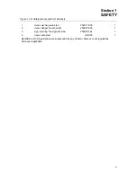
Страница 7: ...ers 1 decal warning auto start 250017 903 1 2 decal danger breath air I 250027 935 1 3 sign warning food grade lube 250003 144 1 4 decal auto start 041065 1 I OSHA and FDA guidelines are superseded by any Federal State or Local regulations whenever applicable ...

Страница 8: ...Section 1 SAFETY 4 NOTES ...

Страница 9: ...panel is shown in Figure 2 1 The controller panel consists of Display Screen for displaying machine status START pad for machine startup STOP pad for stopping machine operation and for clearing fault messages while the machine is stopped UP arrow and DOWN arrow pads for navigation through the various panel displays and for changing parameter values ENTER pad for selecting and accessing various scr...

Страница 10: ...n the motor and compressor to show proper motor compressor rotation 4 If the motor shaft is not turning in the proper direction disconnect the power to the starter and exchange any two of the three power input leads Refer to the Compressor Operator s Manual 5 Perform above steps 1 3 again to confirm proper motor compressor rotation Variable speed drive VSD packages do not require a main motor dire...

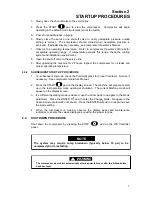
Страница 11: ...QUENT START UP PROCEDURE 1 On subsequent start ups check the fluid sight glass for proper fluid level Service if necessary See compressor Operator s Manual 2 Press the START pad on the display screen The machine will prepare to start up in the last operating mode existing at shutdown The current Machine mode will appear on the display screen 3 If a different operating mode is desired use the arrow...

Страница 12: ...Section 2 STARTUP PROCEDURES 8 NOTES ...

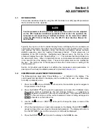
Страница 13: ...ters can be modified by the user The bottom line of the display will show the current value or setting of the control parameter Section 3 2 provides general steps to modifying the compressor control parameters A description of each user modifiable parameter is provided in Section 3 3 3 2 COMPRESSOR ADJUSTMENT PROCEDURES The following steps apply while Show Setting is indicated in the display The c...

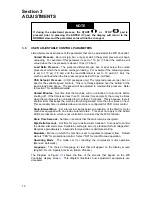
Страница 14: ... machine from being started more than four times an hour This secondary timer is disabled when a machine is configured for VSD motor control Drain Interval Mins Set interval in minutes between activation of the drain cycle for machines equipped with an electric solenoid drain This does not apply to the Sullair SCD zero loss drain which is not controlled or monitored by the WS Controller Drain Time...

Страница 15: ...ng Unload Pressure Show Setting Load Delta Pressure Change Setting Load Delta Pressure Show Setting Unload Minutes Change Setting Unload Minutes Show Setting Drain Interval Mins Change Setting Drain Interval Mins Show Setting Drain Time Seconds Change Setting Drain Time Seconds Show Setting Wye Delta Seconds Change Setting Wye Delta Seconds Show Setting Modulate Change Setting Modulate Show Settin...

Страница 16: ...te control This may be wired to a remote switch timer or other controls to halt operation of the compressor as desired To enable remote control of the compressor 1 Wire the remote contact to junction J4 7 and any vacant J3 terminal 2 Access the PC User Interface software At the User Adjustments display screen select one of the following sequencing modes Remote Hours or Com Number Remote operation ...

Страница 17: ...ect the parameter that is displayed on the screen After adjusting the desired parameter value using the UP or DOWN arrow pads the ENTER pad selects the parameter value displayed on the screen and saves it as the new value 4 3 INDICATOR LED DESCRIPTION Four LED s on the WS Controller Panel provide indication of the general state of the machine Power On Indicator GREEN LED Lights whenever power is a...

Страница 18: ... 1 The top line of the display screen in Normal View shows the discharge pressure and the internal temperature of the compressor package The lower line of the Display Screen displays the current compressor operating mode Figure 4 1 Display Screen Normal View Example 118 psi 70 F AUTOMATIC Under normal operating conditions the lower line of the Controller Display Screen will alternately display the...

Страница 19: ... are conditions and limits that can be modified by the operator This view is accessed using the navigational arrows and is indicated by the text Show Setting appearing on the first line of the display screen See Figure 4 3A Pressing Enter at the Show Setting screen accesses the Change Mode This mode is indicated by the text Change appearing as reverse characters on the first line of the display sc...

Страница 20: ...OFF appearing in the lower line of the display window This mode indicates that the compressor and motor have been turned off under normal conditions When in this mode the machine will not operate until the START pad is pressed Fault mode Indicated by the word FAULTED appearing in the lower line of the display window This mode indicates that a machine problem has occurred causing the controller to ...

Страница 21: ... contact is close NOTE The machine may start at any time when conditions are met Standing by Displayed when the compressor is stopped and waiting for proper conditions before restarting Faulting Displayed as a fault condition is occurring Faulted Displayed after a fault condition has occurred Waiting for Blowdown Displayed when the compressor is waiting for the sump to reach a set minimum pressure...

Страница 22: ...he time frame noted in the machine operation specifications Change Separator The compressor oil separator should be changed within the time frame noted in the machine operation specifications Change Air Filter The compressor air filter should be changed within the time frame noted in the machine operation specifications Analyze Oil An oil analysis should be scheduled per machine operation specific...

Страница 23: ...es that the compressor Temperature at temp probe location 1 is approaching the set low limit Low Temperature 2 Indicates that the compressor Temperature at temp probe location 2 is approaching the set low limit Low Temperature 3 Indicates that the compressor Temperature at temp probe location 3 is approaching the set low limit Sequence Comm Error Indicates a communication problem exists between th...

Страница 24: ...ion between the controller and the PC User Interface has occurred Low AN0 Sensor AN0 AN9 Device assigned to sensor input AN0 thru AN9 temp probe transducer unit etc or wiring between the device and the controller module has resulted in a short circuit Low Line Pressure The line pressure has fallen below the set low limit Low Oil Pressure Compressor oil pressure has fallen below the set low limit L...

Страница 25: ...bles listed All available data concerning the trouble should be systematically analyzed before undertaking any repairs or component replacement procedures Always perform a detailed visual inspection when a machine problem occurs prior to attempting any repairs Doing so may avoid unnecessary repair and or additional damage to the compressor Always remember to a Check for loose wiring b Check for da...

Страница 26: ...w consult power company Change Air Filter Change Oil Change Oil Filter Change Separator Service interval has expired Maintenance due Select Maintenance from menu to see service due and part numbers Controller Watchdog Controller fault Contact Sullair Factory Service E Stop Push Button E Stop Button Active Faulty E Stop Button Release button Check wiring High Air Filter ΔP Differential Pressure Acr...

Страница 27: ...s and shell If plugging persists use cleaner water Check sensor and wiring Illegal State Controller fault Contact Sullair Factory Service Internal Com Error Module Network Error Communication has failed between the Display Module I O Module and other modules Check wiring Low analog input AN0 thru AN9 Sensor Pressure Transducer Temp Probe etc or Wiring Failure Check sensor wiring Check sensor Low L...

Страница 28: ... Check sequence settings of all compressors in the sequence Starter Aux Contact Starter failed to operate Faulty auxiliary contact Check starter and control wiring Check contact and contact wiring UI Voltage too High Controller fault Contact Sullair Factory Service UI Voltage too Low Controller fault Contact Sullair Factory Service User Option Switch User furnished switch has operated Check functi...

Страница 29: ...Section 5 TROUBLESHOOTING 25 ...

Страница 30: ......

Страница 31: ...BP 82 42602 Montbrison Cedex France Telephone 33 477968470 Fax 33 477968499 www sullaireurope com SULLAIR CORPORATION 3700 East Michigan Boulevard Michigan City Indiana 46360 U S A www sullair com Telephone 1 800 SULLAIR U S A Only or 1 219 879 5451 Fax 219 874 1273 CUSTOMER CARE for Parts and Service 1 888 SULLAIR 785 5247 219 874 1835 Specifications Subject To Change Without Prior Notice E05 Pri...

Отзывы: