background image

Содержание XT 1988

Страница 1: ...II t E CT rr0 N Jl t t J i...

Страница 2: ...ake changes at any time without prior notice FUJI HEAVY INDUSTRIES LTD How to use this manual This service manual is divided into four volumes Each volume consists of Section 1 Section 2 3 Section 4 5...

Страница 3: ...m j 2 6 j f 7 r w ti SySt Rl 24fll fStue 2 9E xhau l ysteJti 2 D Clutch 2 tl Engine and TranPni SioQ l IIoulltfA9Svstt altfall ttiisSitnland QiffeT lt iat i Automati Tf i s nd Un r I tra sn im n COftt...

Страница 4: ...SUBARU 1988 SrERV CE MAINJUJAlL QUICK REFERENCE INDEX j GENERAL SECTION SPECIFICATIONS 1 1 1 2 GENERAL INFORMATION 1 3 PRE DELIVERY INSPECTION 1 4 PERIODIC MAINTENANCE SERVICES 1 5 SPECIAL TOOLS 1 6...

Страница 5: ...ric Control System Exhaust Gas Recirculation Front wheel drive 2WD Federal Motor Vehicle Safety Standards GVWR HI HP IG COIL IG SWITCH INT lIP LH LO LSD MPFI MT PCV PHV PIN PIS pulley RAD FAN R DEF RH...

Страница 6: ...and Label Locations 1 3 9 Inspect Brake Line and Check Operation of Parking and Service Brake System 1 5 25 Installation of Steering Components 1 4 15 Jack Installation 1 4 10 Lifting Towing and Tie d...

Страница 7: ...SPECIFICATIONS 55i1 l 1 I1 I XT 1988...

Страница 8: ...555 2 455 2 455 1 000 1 005 2 1 105 2 1 160 2 435 2 560 1 640 1 695 1 405 1 525 1 445 1 450 985 995 1 1 085 1 1 145 2 390 2 520 870 870 1 920 1 920 690 690 1 520 1 520 1 560 1 560 3 440 3 440 4WD FWD...

Страница 9: ...ype and manufacturer For U S A W20EPR U11 or W16EPR Ul1 W22EPR Ul1 Nippondenso RN9YC 4 or RN 11 YC 4 Champion For Canada RN9YC 4 or RN11 YC 4 Champion Maximum output HP rpm 97 5 200 145 5 200 Maximum...

Страница 10: ...3 S 3 2 Minimum turning circle m ft 9 7 31 81 at tireI 10 8 3S 41 at bumper 10 4 34 1 at tire 11 3 37 11 at bumper Front 1 2 1 Suspension Rear 3 4 3 Service brake system Dual circuit hydraulic with v...

Страница 11: ...2 fluid Capacity AT differential gear oil Q US qt Imp qt 1 4 1 5 1 2 4WD rear differential Q US qt Imp qtl gear oil Power steering fluid Q US qt Imp qt Engine coolant Q US qt Imp qt 5 5 5 8 4 8 01 4W...

Страница 12: ...TIONS 2 VEHICLE IDENTIFICATION NUMBERS V I N 7 IDENTIFICATION NUMBER AND LABEL LOCATIONS 9 THEFT PREVENTION 11 RECOMMENDED FUEL LUBRICANTS SEALANTS AND ADHESIVES 13 TIGHTENING TORQUE OF STANDARD BOLTS...

Страница 13: ...car body be sure to chock the tires remaining in contact with the ground 3 Keep the parking brake applied when working on the vehicle Set the shift lever to REVERSE when the parking brake cannot be ap...

Страница 14: ...heel speed Therefore an adapter which doubles the speed is neces sary L1 407 Fig 4 Adapter method Use the adapter method only when the jack up method cannot be employed at the service garage 3 2 Testi...

Страница 15: ...ipment Speedometer tester 1 Wheel blocks 2 ADAPTER 499827100 1 Since the speedometer detector is on the engine side of the center differential if the front wheels are locked the vehicle s speedometer...

Страница 16: ...rotating faster than normal Check the transmission oil which also serves as the center differential oil and add if oil level is low Keep maximum speed below 50 km h 31 MPH and for less than 1 minute 5...

Страница 17: ...onfirmation of differential lock cancellation CV When the vehicle has a large air spoiler skirt on it wrap the tow rope with a rag to prevent the rope from scratching the air spoiler Tow the vehicle w...

Страница 18: ...h the front wheels raised or on rollers brake tester chassis dynamometer etc always set the car in the FWD mode To set the car in the FWD mode disconnect the 4WD circuit by inserting a fuse in the FWD...

Страница 19: ...eck digit othru 9 and X varies L _ _ _ _ _ _ _ _ _ _ _ _ _ Weight class and restraint type 2 3 001 to 4 000 Ib GVWR with passive restraint B 3 001 to 4 000 Ib GVWR without passive restraint For CANADA...

Страница 20: ...f the engine compartment main case MT or converter housing AT _______ _V IN l Ll 419 Fig 21 2 Engine Serial Number The engine serial number is stamped on the right side of the crankcase at the front L...

Страница 21: ...plate is stuck near the driver s side door striker Fig 24 5 Vehicle Emission Control Information Labels L1 223 Vehicle emission control information labels are stuck under the engine hood L1 224 Fig 25...

Страница 22: ...led parts shown below Additionally the R DOT label is stuck or t R DOT is stamped on the main spare parts shown below 1 T P label and R DOT label A T P label 8 R DOT label 1 3 L1 424 L1 425 For engine...

Страница 23: ...1 3 GENERAL INFORMATION CD Front hood Fender 3 Door I c _ _ bJ Front bumper Rear bumper Fig 30 Rear quarter j Trunk lid Engine Transmission Manual Transmission Automatic Transmission 12 LJL 2700 cc...

Страница 24: ...gear oil GL 5 4WD rear differential gear oil Automatic transmission DEXRON II For power steering fluid and power steering fluid Recommended fluid Manufacturer B P CALTEX ATF CASTROL Dexron II MOBIL S...

Страница 25: ...etc Control cables and carburetor linkages Silicolube G 30M subject to cold weather water pump Grease PIN 004404002 impeller door latch striker battery terminals etc Dow Corning Molykote No 7439 Cont...

Страница 26: ...sity No designated by Subaru c SAE 50W 30 is not recommended for sustained high speed driving d If vehicle is used in desert areas or areas with very high temperatures or for other heavy duty applicat...

Страница 27: ...st water and dust entry Butyl Rubber PIN 000018901 through weatherstrips grommets etc Sealant Weatherstrips and other rubber parts 3M s Cemedine 5430L plastics and textiles except soft vinyl EC 1770 p...

Страница 28: ...7 TC 003 1 00 1 80 7 2 13 0 Fig 33 10 22 6 36 3 2 30 3 70 16 6 26 8 Including bolt or nut with washer or spring washer 12 3S 2 64 7 only 4 00 6 60 28 9 47 7 The mark is embossed on the bolt head as fo...

Страница 29: ...ow and tie down the vehicle at the designated positions 1 Garage Jack IFRONT I Crossmember F Fig 34 Fig 35 a When jacking up the vehicle place chocks to hold wheels b After jacking up the vehicle with...

Страница 30: ...support body when you have to get under the car b Block the wheels diagonally using wheel chocks c Make sure the jack is set at the correct position on the flange of side sill d Be careful not to set...

Страница 31: ...ositions as those of pantograph jack b Be careful not to set the lift at the air flap portion 5 Towing and Tie down Hooks Avoid towing another car using front towing hooks IFront I rl dl bD1t 3 B o gg...

Страница 32: ...PRE DELIVERY INSPECTION SUBARU 1988 Page PRE ROAD TEST INSPECTION 3 ROAD TEST INSPECTION 19 POST ROAD TEST INSPECTION 24...

Страница 33: ...FOR LOOSENESS AND TIRE INFLATION PRESSURE 11 014 SEAT ADJUSTER AND SEAT BELTS 11 015 FUSES 13 o 16 LIGHTS AND SWITCHES 13 o 17 PREPARATION FOR UNDERSIDE INSPECTION See p 18 in Chap 1 3 _ 018 INSTALLA...

Страница 34: ...OPERATION CHECK POINTS 1 Operation of hood release and lock 2 Condition of lock 3 Fitting of hood 1 Check the operation of hood release and lock Fig 1 _ safetY lever Fig 2 2 Check the condition of lo...

Страница 35: ...xcessive force when pulling the outer handle b If the lock cylinder does not function properly it must be replaced with a new one However if the door lock s opera tion is just unsmooth it may be corre...

Страница 36: ...pulled from the inside of the passenger compartment Also make sure that it can only be released Recommended brake fluid from the outside with the key L 1 154 Fig 12 5 FMVSS No 116 fresh DOT3 or 4 bra...

Страница 37: ...t with skin eyes or clothing Especially contact with eyes flush with water for 15 minutes and get prompt medical attention c Batteries produce explosive gasses Keep sparks flame cigarettes away d Afte...

Страница 38: ...Be sure to wait until the engine cools down before opening the radiator cap When reserve tank is empty Fig 19 Q check engine FULL L1 545 Fig 17 3 Inspect for water leakage and hose damage When retight...

Страница 39: ...n replenishing oil it does not matter if the oil to be added is a different brand from that in the engine however use oil having the API classification and SAE viscosity No designated by SUBARU 8 TRAN...

Страница 40: ...if necessary 1 Place the vehicle on level ground and check with the engine stopped 2 Remove the filler plug of the differential 3 011 level should be kept at the bottom of the filler hole 4 If the oil...

Страница 41: ...an eyeleteer or similar tool adjust the direction of the nozzle be careful not to damage the nozzle hole 3 Check the operation of windshield wiper and washer L1 529 If the level is not to the filler...

Страница 42: ...he wheel nuts be sure to use a torque wrench 2 Check front seat operation Sliding and tighten the nuts to the specified torque Fig 32 Fig 31 2 Adjust tire inflation pressure and check tire specificati...

Страница 43: ...lding operation e Unlock Lock L5 645 Fig 39 4 Check seat belts and their fit The seat belt warning light on the instrument panel comes on for approximately six seconds with the ignition starter switch...

Страница 44: ...SPARE I ISPARE I IRAD FAN II IHEAD LH I CATCHER I IWIPER II IHEAD RH Ll 241 Fig 40 16 LIGHTS AND SWITCHES CHECK POINTS 1 Visual inspection of lights installation damage dirty lenses water inside etc 2...

Страница 45: ...The lever will return automatically once it is released The headlight flasher works independently of the lights switch Do not hold the lever for more than just afew seconds L1 536 Fig 44 14 Turn signa...

Страница 46: ...e as it discharges the battery rrr L 4 SO Fig 47 Parking light switch When the switch knob is pushed the parking lights all go on regardless of the ignition switch position r I L 4 S1 Fig 48 15 CHECK...

Страница 47: ...st pipe 13 23 N m 1 3 2 3 kg m 9 17 ft lb Rear exhaust pipe to muffler 42 52 N m 4 3 5 3 kg m 31 38 ft Ib Front exhaust pipe to bracket 25 34 N m 2 5 3 5 kg m 18 25 ft Ib Tail pipe cutter to muffler 2...

Страница 48: ...ION Purge line Vacuum line Canister Purge line Vacuum line Canister Throttle body lntakemanifold Fuel injector Fuel delivery tine 2 way valve Throttle body Intake manifold Fuel injector Fuel delivery...

Страница 49: ...er com pressor has stopped Check if car returns to the specified NORMAL position within 30 seconds 6 If abnormality is noted in steps 1 through 5 above refer to Chapter 4 1 and repair as necessary 22...

Страница 50: ...ut when the parking brake lever is released 2 Make sure that each indicator light operates normally and corresponds to its respective device Headlight beam indicator light Hazard warning indicator lig...

Страница 51: ...eedometer 45 B5 6 Voltmeter 7 35 95 25 105 _ 101010101010101 Fuel gauge 8 Warning lights 5 115 o 125 f i F UNL D OD Y 9 Low fuel warning e light MPH IQIJKIIlQl 35 20 STDP BRAKE CH ECK LAMP IO FLUID l...

Страница 52: ...safe area 2 Press the brake pedal in two or three times and keep it fully depressed Make sure that the brake can be kept that way for at least five seconds Also check for air in the brake system or br...

Страница 53: ...f pressure holding valve PHV cable If the vehicle does not start properly it should be corrected by following case A or case B Case A When the hill holder releases after the clutch pedal is engaged th...

Страница 54: ...3 while the vehicle is moving straight ahead b Do not shift the drive selector lever when the wheels are spinning or slipping 5 Operation of steering and position of steering wheel 1 Check the steerin...

Страница 55: ...lower than 55 km h 35 MPH for at least five seconds to check if HIGH pilot lamp instead of NORMAL pilot lamp comes on again 4 Stop car and move height control switch to NORMAL Check if car is set to t...

Страница 56: ...luid is SPECIAL POWER STEERING FLUID XT6 Be sure to use the recommended fluid b When power steering fluid is added be careful not to allow any dust into the tank 3 TOE 1 To check the toe make sure tha...

Страница 57: ...he measured toe or sideslip value is not within the standard range adjust it as follows 1 Loosen the lock nut on the right and left tie rod ends and adjust the right and left tie rods simultaneously T...

Страница 58: ...ce may be scratched if the surface is rubbed with sand or other hard particles which may be attached to the protective agent Check the whole vehicle body for stains flaking damage caused by transporta...

Страница 59: ...wise the transparent resin plate on it may become cloudly due to the formation of scratches 5 Check the interior and exterior equipment to make sure that they are installed securely Also make sure tha...

Страница 60: ...LTER AND INSPECT FUEL SYSTEM HOSES AND CONNECTIONS 15 7 AIR FILTER ELEMENTS AIR CLEANER PCV AIR FILTER 16 8 SPARK PLUG 17 9 TRANSMISSION DIFFERENTIAL FRONT AND REAR LUBRICANTS GEAR OIL 18 10 AUTOMATIC...

Страница 61: ...dal free 15 Clutch and hill holder system I I I I play at 1 600 km 1 000 miles 16 Steering and suspension I I I I See NOTE gl 17 Grease on front and rear wheel bearings I a When the vehicle is used un...

Страница 62: ...RVAL Nu mber of months or km miles whichever occurs first Months 7 5 15 22 5 30 37 5 45 52 5 60 x 1 000 km 12 24 36 48 60 72 84 96 x 1 000 miles 7 5 15 22 5 30 37 5 45 52 5 60 0 m 2 Check drive belt t...

Страница 63: ...pulley 2 When replacing belt with a new one adjust its tension to the ALT Alternator pulley specification and then readjust it to the same specification after running engine for 5 minutes in consider...

Страница 64: ...4 5 kg m 25 33 ft Ib Lock nut Adjusting bolt Fig 5 CIP Crankshaft pulley WIP Water pump pulley AIC Air conditioner compressor pulley ALT Alternator pulley liP Idler pulley L1 552 5 Tightening torque...

Страница 65: ...r by loosening eight 6 mm bolts 10 Remove timing belts 1 Loosen bolts securing tensioner on the side of 1 and 3 cylinders and move tensioner upward completely Then temporarily tighten bolts Use specia...

Страница 66: ...in steps 1 and 2 above 9 Rotate crankshaft clockwise one turn and align center line of scribed three lines on flywheel with timing mark on flywheel housing 10 Install crankshaft sprocket CPo 11 Align...

Страница 67: ...ft Ib 4 Install water pump pulley Assemble water pump pulley and pulley cover and temporar ily tighten bolts 5 Install oil level No 2 guide ASSY and oil level gauge CPo Coat O ring with engine oil whe...

Страница 68: ...84 96 x 1 000 miles 7 5 15 22 5 30 37 5 45 52 5 60 mmmmmIII mm 2 Open engine oil filler cap for quick draining of the engine oil Fig 11 3 Tighten engine oil drain plug after draining engine oil Tighte...

Страница 69: ...lications the following viscosity oils may be used 30 40 10W 50 20W 40 2OW 50 c When replenishing oil it does not matter if the oil to be added is a different brand from that in the engine however use...

Страница 70: ...areful not to damage seal rubber 4 Tighten more approximately two thirds turn after the seal rubber contacts the oil pump case Do not tighten excessively or oil may leak 5 After installing oil filter...

Страница 71: ...k Fig 16 12 9 Carefully pour pr pared coolant from radiator filler port to neck of filler then pour into reserve tank up to FULL level Coolant capacity Pour up to FULL level Approx 5 5Q 5 8 US qt 4 8...

Страница 72: ...86 104 122 Coolant temperature c OF L1479 If the coolant temperature is 25 C 77 F and its specific gravity is 1 049 the concentration is 35 point A the safe operating temperature is 14 C 7 F point Bl...

Страница 73: ...or reserve tank and hoses for damage or clogging 2 Check the hose connections for leakage 3 Check the valve spring and packing in the cap for damage 4 Check rubber seal on cap for tears cracks or dete...

Страница 74: ...hose clamp screw to the specified torque Tightening torque 1 0 1 5 N m 0 1 0 15 kg m 0 7 1 1 ft Ib 4 If the hose is damaged at the clamping portion replace the hose with a new one 5 If the hose clamp...

Страница 75: ...ring to this filter paper forms porous laminations with the viscous liquid which function as a filtration layer to reduce dust penetration into the filter paper If this filter paper is cleaned the fil...

Страница 76: ...1 mm 0 039 0 043 in Spark plug thread Dia 14 mm 0 55 in Pitch 1 25 mm 0 0492 in Fig 26 A9 163 17 MAINTENANCE INTERVAL Number of months or km miles whichever occurs first Months 7 5 15 22 5 30 37 5 45...

Страница 77: ...evel L1 556 18 MAINTENANCE INTERVAL Number of months or km lmiles whichever occurs first Months 7 5 15 22 5 30 37 5 45 52 5 60 x 1 000 km 12 24 36 48 60 72 84 96 x 1 000 miles 7 5 15 22 5 30 37 5 45 5...

Страница 78: ...r of these two marks ATF level gauge hole also serves as fluid filler Do not fill the fluid above upper point of level gauge High mark Low mark L1 557 Fig 30 Recommended automatic transmission fluid A...

Страница 79: ...km milesl whichever occurs first Months 7 5 15 22 5 30 37 5 45 52 5 60 x 1 000 km 12 24 36 48 60 72 84 96 x 1 000 miles 7 5 15 22 5 30 37 5 45 52 5 60 m m a Avoid mixing different brands of brake flu...

Страница 80: ...ce of approximately 294 N 30 kg 66 Ib and hold it there for approximately 20 seconds At this time check pedal to see if it shows any unusual move ment Visually inspect bleeder screws and brake pipe jo...

Страница 81: ...37 15 22 5 30 37 5 24 36 48 60 15 22 5 30 37 5 D D Pad thickness including back metal Front Except XT6 18 0 71 Standard XT6 22 0 87 Except XT6 Wear limit 7 5 0 295 XT6 Wear limit Except XT6 excluding...

Страница 82: ...xcept XT6 16 0 63 Wear limit 8 5 0 33 XT6 20 0 79 Th ickness of disc Ll l72 Fig 38 Disc rotor runout Limit 0 10 mm 0 0039 in Measure the disc rotor runout at a point less than 5 mm 0 20 in from the ou...

Страница 83: ...15 22 5 30 37 5 45 52 5 60 x 1 000 km 12 24 36 48 60 72 84 96 x 1 O mil es 7 5 15 22 5 30 37 5 45 52 5 60 D D 2 Check brake drum for wear dents or other damage If the inside surface of brake drum is s...

Страница 84: ...pes hoses during driving and loose connections clamps 3 Check any trace of fluid leakage scratches etc on master cylinder wheel cylinder pressure control valve and hill holder When the brake fluid lev...

Страница 85: ...feel of the pedal operation If air appears to exist in the line bleed it from the system 5 Check for even operation of all brakes using a brake tester or by driving the vehicle for a short distance on...

Страница 86: ...ngine side Air should not flow out of hose Replace both check valve and vacuum hose if check valve is faulty Engine side of vacuum hose is indicated by marking II ENGINEI as shown Brake booster Engine...

Страница 87: ...replacing clutch cable vvith new one and or making free play adjustment of clutch pedal make adjustment of hill holder system without fail as follows b After replacing clutch cable and or pressure ho...

Страница 88: ...Fig 54 PERIODIC MAINTENANCE SERVICES 1 5 L 470 29 b Replace pressure hold valve PHV return spring of PHV or PHV cable with new one if they are defective and or damaged...

Страница 89: ...t be pulled to either side while driving on a level surface 30 MAINTENANCE INTERVAL Nu mber of months or km miles whichever occurs first 1 Months 7 5 15 22 5 30 37 5 45 52 5 60 x 1 000 km 12 24 36 48...

Страница 90: ...Power 926230000 SPANNER steering STEERING GEAR BOX Fig 59 3 From that position turn back adjusting screw 15 and then tighten lock nut securely Tightening torque 29 49 N m 3 0 5 0 kg m 22 36 ft Ib Hol...

Страница 91: ...cified range of indicator by using a syri nge or the like Recommended fluid Manufacturer B P CAlTEX CASTROl ATF Dexron II MOBil SHEll TEXACO XT6 32 IDEMITSU Fluid capacity Recommended fluid SPECIAL PO...

Страница 92: ...arbox and the rod 2 Clips are fitted outside of A 8 and C positions of boot 3 Projection of boot is fitted in hole on A groove of gearbox to prevent boot rotating 4 800t does not have crack hole Rotat...

Страница 93: ...31 46 ft Ib Bolt B two 20 29 N m 2 0 3 0 kg m 14 22 ft Ib Bolt C three 18 22 N m 1 8 2 2 kg m 13 16 ft Ib Bolt D three 29 49 N m 3 0 5 0 kg m 22 36 ft Ib 34 Fig 68 Tightening torque Bolt A four 23 42...

Страница 94: ...ed parts Suspensions components Front strut assembly cross member transverse link etc Rear shock absorber inner arm outer arm etc Body parts to which suspensions are installed When no components are d...

Страница 95: ...emove bolt linking lower end of shock absorber to inner arm c Then loosen outer arm mounting bolts shown in Fig 5 d If camber angle is excessive in ffi direction use a piece of wood as a lever and cha...

Страница 96: ...iaphragm Inspect every 24 000 km 15 000 miles or 15 months whichever occurs first 1 After loosening wheel nuts jack up vehicle until all four wheels are off ground according to instructions in Pre Del...

Страница 97: ...by hand swing it in and out to check bearing free play 3 Loosen wheel nuts and remove front wheel 4 If bearing free play exists in step 2 above attach a dial gauge to hub and measure axial displacemen...

Страница 98: ...nect brake pipe from brake hose Fit air breather cap onto end of brake hose to prevent brake fluid from pouring out 11 Remove brake assembly from trailing arm 12 Remove bolt holding inner bushing of i...

Страница 99: ...24 Mount inner arm to vehicle body Tightening torque Inner bush bolt 74 93 N m 7 5 9 5 kg m 54 69 ft Ib Inner and outer arms connecting bolts 118 147 N m 12 0 15 0 kg m 87 108 ft Ib 25 Install rear b...

Страница 100: ...on nut and spindle 30 Install packing to rear spindle and mount D O J or B J on rear drive shaft onto spindle with trailing arm lowered all the way When mounting mate the spline teeth properly so tha...

Страница 101: ...RANSMISSION AND DIFFERENTIAL TOOLS 4 AUTOMATIC TRANSMISSION AND DIFFERENTIAL TOOLS 9 REAR WHEEL DRIVE SYSTEM 4WD MODELS TOOLS 11 SUSPENSION TOOLS 13 WHEELS AND AXLES TOOLS 14 STEERING SYSTEM TOOLS 0 1...

Страница 102: ...MER CAMSHAFT HOLDER INSTALLER For removing of valve guide For reaming of valve guide Used to hold camshaft when Used to install camshaft oil seal press fitting distributor gear to A5 147 498267100 CYL...

Страница 103: ...3 499437100 499567000 BELT TENSION WRENCH CP INSTALLER When installing timing belt used Used to install crankcase front oil to apply the specified torque to seal camshaft pulley so as to get the speci...

Страница 104: ...lve guides rubber boot of adjuster COMPL for easy installation of belt 2700 cc model A5 149 L1 568 Manual Transmission and Differential Tools 398406200 398791600 398791700 STAND REMOVER II REMOVER II...

Страница 105: ...12 175 L1 105 498077000 498147000 498247001 5TH DRIVE GEAR REMOVER DEPTH GAUGE MAGNET BASE 5th driven gear Main shaft axial end play Backlash between side gear and adjustment pinion Hypoid gear backle...

Страница 106: ...L1 110 498937000 499277000 499277100 499277200 TRANSMISSION HOLDER INSTALLER BUSH 1 2 INSTALLER INSTALLER Transmission main shaft lock nut Drive pinion 1st driven gear thrust plate For press fitting...

Страница 107: ...188 499917500 499927000 499927100 499987300 DRIVE PINION GAUGE ASSY HANDLE HANDLE SOCKET WRENCH 50 Drive pinion shim adjustment Transmission main shaft Transmission main shaft To remove the driven ge...

Страница 108: ...4WD Drive pinion Rear drive shaft 4WD FWD FWD Gu d i o Press i A12 181 A12 182 A11 025 A12 183 899864100 899874100 899884100 899904100 REMOVER INSTALLER HOLDER REMOVER Transmission main shaft Transmi...

Страница 109: ...209 A13 211 398673600 399520105 399703600 399780111 COMPRESSOR SEAT PULLER WRENCH Snap ring for clutch piston Roller bearing Differential Used to install band servo piston Axle shaft oil seal holder r...

Страница 110: ...ER Used when checking oil pressure _ Used to tighten loosen M30 lock Used to extract axle drive shaft Drive pinion oil seal etc nut for drive pinion from differential ASSY Used when measuring tooth Us...

Страница 111: ...tem 4WD Models Tools 397471600 HANDLE DRIFT KIT Front and rear bearing cup 6 10_ 1 J D 1 HANDLE 398477701 I 2 DRIFT 3984777021 3 DRIFT 2 398477703 ST 143 398237700 GAUGE Side bearing oA 14 086 3981777...

Страница 112: ...398507703 398507704 DUMMY COLLAR BLOCK Pinion height and Preload Pinion height and Preload adjustment adj ustment 0 A14 082 A14 083 399527700 399780104 PULLER SET WEIGHT Side bearing cone Front bearin...

Страница 113: ...IR PIPE REMOVER Used to remove and install coi I spring Camber caster gauge Used to disassemble and assemble Used to disconnect air pipe from front strut ASSY or front air jOint suspension ASSY Except...

Страница 114: ...ve front axle shaft or brake drum 4WD A16 053 1 AXLE SHAFT INSTALLER 922431000 can be used instead of this INSTALLER 925130000 922431000 AXLE SHAFT INSTALLER Used to install front axle shaft into hous...

Страница 115: ...nto Used as a bearing pad when housing bearing housing pressing hub into place 2700 cc model 2700 cc model 2700 cc model L1 579 L1 580 L1 581 927140000 AXLE SHAFT PULLER PLATE Same as plate 2 included...

Страница 116: ...0000 BUSH A REMOVER Used to remove bush A from VGR Variable Gear Ratio steering gearbox unit For VGR steering gearbox Ll 129 3 SPANNER 926230000 for power steering can be used instead of this tool 2 S...

Страница 117: ...teering body ASSY backlash of gearbox Removal and installation of tie rod Measurement of rotating resistance of gearbox ASSY L1 133 926290000 REMOVER INSTALLER A INSTALLER INSTALLERC L1 281 926300000...

Страница 118: ...oil seal to steering body ASSY L1 197 926980000 GUIDE Shaft and bearing ASSY of oil pump L1 497 Newly adopted tool 927020000 JIG MOTOR PUMP ASSY Used to over haul MOTOR PUMP ASSY L1 198 L1 571 926420...

Страница 119: ...1 16 in Rear drum brake f Jd e I A 17 163 926440000 SPACER Used as a set with WRENCH 926430000l Attach this tool to WRENCH using two 6 mm dia bolts length less than 15 mm l All models L1 144 All model...

Страница 120: ...PIPE SHAFTSEALINSTALLER CLUTCH ARMATURE REMOVER Used with OIL SEPARATOR Used with 01 L SEPARATOR For removing and installing shaft For clutch disassembly seal fjO in9 EO J I ST 179 ST 180 L4 541 A26 0...

Страница 121: ...SPECIAL TOOLS 926190000 INJECTOR NEEDLE For discharging and charging gas Q II L4 547 925610000 WRENCH Door hinge ST 166 927150000 ENGINE SUPPORT ASSY For supporting engine 2700 cc model L1 572 21 9266...

Страница 122: ...1 f f f f f 1 1 f d 1 1 1 1 1 1 1 1 f 1 f 1 r 1 1 1 1 1 1 I 1 Publication No G 140BE CD Issued July 1987 A Printed in Japan M 4 2...

Страница 123: ......

Страница 124: ...changes at any time without prior notice FUJI HEAVY INDUSTRIES LTD How to use this manual This service manual is divided into four volumes Each volume consists of Section 1 Section 2 3 Section 4 5 and...

Страница 125: ...ystem 2 6 2 7 Fuel Injection System 2 8 Fuel System 2 9 Exhaust System 2 10 Clutch 2 11 Engine and Transmission Mounting System 3 1 Manual Transmission and Differential 3 2 Automatic Transmission and...

Страница 126: ...ENGINE LUBRICATION SYSTEM 2 4 ENGINE COOLING SYSTEM 2 5 2 6 FUEL INJECTION SYSTEM 2 7 FUEL SYSTEM 2 8 EXHAUST SYSTEM 2 9 CLUTCH 2 10 ENGINE AND TRANSMISSION 2 11 MOUNTING SYSTEM TRANSMISSION AND DIFFE...

Страница 127: ...titude Hydraulic Lash Adjuster Idle Adjusting Screw Inside Diameter Idle Ignition Ignition ON Ignition Switch InputlOutput Kick Down KDLH LED Led LH LSD LlU MPFI MPS MP T MT 0 0 OHC OIP OP OS OVRIC O...

Страница 128: ...ve 3 2 35 Crankcase Emission Control System 2 1 5 Low Reverse Brake 3 2 16 Crankshaft and Piston 2 3 96 Manual Transmission 3 3 7 Crankshaft and Piston 2 3 41 Manual Valve 3 2 34 Cylinder Block 2 3 33...

Страница 129: ...2 152 Servo Piston 3 2 116 Transmission Main Shaft ASSY FWD 3 1 75 Shift Solenoid Duty Solenoid and Valve Transmission Main Shaft ASSY Body 3 2 153 Selective 4WD 3 1 46 Shift Valve A and 4 2 Relay Val...

Страница 130: ...tion General Precautions Schematic Drawing Page 2 2 3 Crankcase Emission Control System 5 DESCRIPTION 5 INSPECTION 6 Ignition Control System 6 Three Way Catalyst 8 Oxidation Catalyst 8 Evaporative Emi...

Страница 131: ...of problems is simply a bad Connec tion in the wiring or vacuum hoses Always make sure that connections are secure and correct 4 Avoid coasting with the ignition turned off and prolonged engine braki...

Страница 132: ...1f Fuel filter Airflowm ter I II li y _J H 4 lll i ith hot wire I I L_ w _ _ i I II U d t o I III I h I 0 at L pev L r rv rv I I I I I I val ve I j I il I L_ y L_ L__ l Oxygen sensor Oxidation catalys...

Страница 133: ...SW J AT I _ 1 w th ank Starter SW I I IIi ill filter v N P e O nly1 III g mper t _ __ angle sensor rangeSW III I Thm tI P 1 IL sensor regulator 6riditioner Air Ii L control A f p t T W lTIL valv _ Vr...

Страница 134: ...s flows into the air cleaner through the connecting hose of rocker cover on 1 3 side and is drawn to the throttle body because under this condition the intake manifold vacuum is not so strong as to in...

Страница 135: ...I J I L 1 L __________ I l 2 1 Distributor i Coolant temper r nsor L2 125 Fig 6 1800 cc Battery 1 I l I r I I I I I I I I I Spark plug rll I Ignition switch I r I r I I MPFI control unit I I I I I I...

Страница 136: ...ure MPF I control unit rAir flow meter Air duct Purge line t Vacuum line Purge control solenoid valve Oxidation Catalyst The basic material is Palladium Pd and Rhodium Rh A thin film of their mixture...

Страница 137: ...acuum_ When the purge control valve is opened the absorbed vapor is introduced from the canister into the throttle body When the engine is not running the purge control valve is closed by the return s...

Страница 138: ...on the filler pipe is sealed at and at the packing pressed against the filler pipe end As vacuum develops in the fuel tank atmospheric pressure forces the spring down to open the valve consequently ai...

Страница 139: ...and To canister purge control valve L2 331 hose to ensure that air does not leak Fig 15 1800 cc 3 Disconnect the evaporation hose from the fuel tank side Orally blow air through the hose to ensure tha...

Страница 140: ...2 1 EMISSION CONTROL SYSTEM AND VACUUM FITTING Vacuum Fitting Fig 17 1800 cc 4WD MT only Fig 18 2700 cc Distributor 12 L2 1264 L2 1265...

Страница 141: ...RU 1988 Page IGNITION TIMING 2 ENGINE COMPRESSION 3 _ INTAKE MANIFOLD VACUUM 3 ENGINE IDLE SPEED 4 OXYGEN 02 SENSOR 6 COOLING SYSTEM 7 HIGH TENSION CORDS 9 CYLINDER HEAD BOLTS 9 OIL PUMP ASSEMBLY 10 W...

Страница 142: ...ff the light 2i To check the ignition timing connect a timing light to 1 cylinder spark plug cord adjust the engine idle speed to the specification and illuminate the timing mark with the timing light...

Страница 143: ...gainst the spark plug hole 8 Perform at least two measurements per cylinder and make sure that the values are correct Fig 3 c E 0 o __ II en a E co 0 u 1 157 11 8 168 1 079 11 0 156 j dard i I I I Lir...

Страница 144: ...correctly adjusted prior to this inspection b Set the gear position at Neutral for MT or lip or liN for AT c Before inspecting the engine idle speed ensure that 1 Vacuum hoses blow by hoses rocker co...

Страница 145: ...llowing chart as a guide Use of leaded gasoline idle CO I L L cr _ l contents 2 Improper compression pressure Fig 5 1 Check the MPFI system Connect a jumper wire and check to see if the CHECK ENGIN E...

Страница 146: ...4301003 to threaded portion of oxygen 02 sensor again and leave it for one minute or more 5 Remove oxygen 02 sensor by using socket and wrench When removing do not force oxygen 02 sensor especially wh...

Страница 147: ...ositIOn I Bend of fin clog leakage LDeformation damage rust I Damage deterioration leakage _ Looseness leakage at connection position w 0_ 1 Damage deterioration leakage I I 0 i I 1 Bend of fin clog I...

Страница 148: ...del 2 Apply a pressure of 157 kPa 1 6 kg cm2 23 psi to radiator to check if 1 Water leaks at around radiator 2 Water leaks at around hoses or connections 8 Fig 9 a Engine should be off b Wipe water fr...

Страница 149: ...3 26 68 6 cord 2 60 6 07 9 Cylinder Head Bolts 1800 cc engine only RETORQUING After completing engine ASSY and mounting engine on car be sure to retighten cylinder head bolts 1 Warm up engine 2 After...

Страница 150: ...olts tighten mounting bolts of intake manifolds Oil Pump Assembly 1800 cc model REMOVAL 1 Open the front hood 2 Disconnect the ground cable from the battery 3 Position the lift arm and raise the vehic...

Страница 151: ...ight belts with a piece of chalk to indicate the direction of advance i ____ Fig 17 L2 825 Fig 18 2 Remove the right timing belt 15 Remove the crankshaft sprocket 16 Remove the left timing belt 1 Loos...

Страница 152: ...timing hole plug 14 Lower the vehicle 15 Connect the grou nd cable to the battery 16 Start the engine 17 Add engine oil to the oil pan 18 Close the front hood and release the Iift arm 2700 cc model R...

Страница 153: ...rom turning Remove the crank pulley 14 Remove the LH RH and CTR belt covers in that order 15 Remove the right timing belt Draw an arrow on the left and right belts with a piece of chalk to indicate th...

Страница 154: ...1 Open the front hood 2 Disconnect the ground cable from the battery 3 Drain the coolant completely 4 Remove the alternator and V belt 5 Disconnect the radiator outlet hose Fig 28 6 Disconnect the wat...

Страница 155: ...l the alternator and V belt 111 Add coolant in the radiator 12 Connect the ground cable to the battery 13 Start the engine and check the coolant level 14 Close the front hood and release the lift arm...

Страница 156: ...Install the crank pulley 5 6 7 Install the water pump pulley Install alternator bracket alternator and compressor Install V belt then adjust belt tension Refer to Chapter 2 3 8 Install the purser ASSY...

Страница 157: ...der Head and Flywheel Housing Camshaft and Timing Belt Belt Cover Electrical Equipment SERVICE PROCEDURE General Precautions Timing Belt and Belt Cover Camshaft and Valve Rocker Cylinder Head Valve an...

Страница 158: ...rotor housing for the oil pump is built into the cylinder block in order to reduce the total length of the engine 3 The cylinder liner is a cast and dry type 2 weight and compact in construction This...

Страница 159: ...ng type gasket and an oil seal washer to reduce the noise level 3 CRANKSHAFT The crankshaft is made from special wrought iron which provides sturdiness All corners of the journals are processed with d...

Страница 160: ...the rocker arms The cam rubbed surface is chilled to increase wear resistance 2 The cam profile is specially designed for this OHC type and features higher output and less fuel consumption 3 The cam...

Страница 161: ...ement with sprocket teeth and smooth and low noise operation The crankshaft sprockets oil pump sprocket and idler are made of sintered alloy_ 3 The camshaft sprockets are made of sheet metal and are c...

Страница 162: ...cc cu in 1 781 1 781 108 68 displacement Compression ratio 9 5 Compression pressure 1 157 11 8 168 at 350 rpm kPa kg cm2 psi UJ Number of piston rings z Pressure ring 2 Oil ring 1 t J Opening 16 BTDC...

Страница 163: ...00 7 015 mm 0 2756 0 2762 in 17 5 18 5 mm 0 689 0 728 in Intake Exhaust 1 3 mm 0 051 in Intake Exhaust Intake Exhaust 0 8 mm 0 031 in 6 950 6 965 mm 0 2736 0 2742 in 6 945 6 960 mm 0 2734 0 2740 in 0...

Страница 164: ...s 92 470 92 480 mm 3 6405 3 6409 in c Standard inner diameter of piston pin hole 20 999 21 009 mm 0 8267 0 8271 in Outer diameter 20 994 21 000 mm 0 8265 0 8268 in c a Standard clearance between pisto...

Страница 165: ...5 mm 0 0098 in US 54 707 54 722 mm 2 1538 2 1544 in Center sro 54 954 54 970 mm 2 1635 2 1642 in 0 03 mm 0 0012 in US 54 924 54 940 mm 2 1624 2 1630 in 0 05 mm 0 0020 in US 54 904 54 920 mm 2 1616 2 1...

Страница 166: ...mm 1 5650 1 5689 in Wear limit 0 15 mm 0 0059 in C CI Cam journal outer diameter Front 37 964 37 980 mm 1 4946 1 4953 in r lIS e Center 48 464 48 480 mm 1 9080 1 9087 in a Rear 47 964 47 980 mm 1 8883...

Страница 167: ...plug n Front engine hanger 18 Cylinder block plug 19 Oil seal Front 20 O ring 21 Service hole plug 22 Oil level gauge guide 23 Oil level gauge 24 Water pump pulley 25 Pulley cover 26 Water pump ASSY 2...

Страница 168: ...Fig 6 12 13 14 15 16 17 18 19 20 21 22 23 Oil ring Crankshaft bearing Front and rear Crankshaft bearing Center Crankshaft pulley V belt Crankshaft sprocket CP Crankshaft sprocket No 2 Woodruff key Co...

Страница 169: ...8 Fig 7 13 2 3 1 Cylinder head RH 2 Cylinder head gasket 3 Engine hanger 4 Timing hole plug 5 Flywheel housing 6 Cylinder head LH 7 Cylinder head gasket 8 Exhaust valve 9 Intake valve 10 Intake valve...

Страница 170: ...4 O ring 5 Camshaft support 6 Timing belt RH 7 Oil seal 8 Camshaft sprocket 9 Camshaft R H 10 Oil relief valve 11 Oil relief spring 12 Oil relief pipe 13 Oil rei ief plug 14 Valve rocker cover gasket...

Страница 171: ...elt cover seal No 3 LH 8 Water pump seal 9 Belt cover seal LH 10 Belt cover RR 11 Belt cover seal No 4 LH 12 Belt cover seal F R 13 Belt cover seal RR 14 Belt cover seal No 2 LH 15 Belt cover No 2 LH...

Страница 172: ...4 Spark plug cord 3 5 S ark plug cord 4 6 Distributor cord Ignition coil 7 Distributor 8 Spark plug 9 Cover 10 Altern 11 starter ator bracket 12 Alternator 13 Nut plate 14 Ad Justing bar T ue N m k 1...

Страница 173: ...iming Belt and Belt Cover REMOVAL 1 Loosen water pump pulley mounting nuts or bolts 2 Loosen two alternator mounting bolts and detach V belt Except air conditioner equipped model 3 Remove water pump p...

Страница 174: ...elt 2 Check the condition of back side of belt if any crack is found replace belt 18 a Be careful not to let oil grease or coolant contact the belt Remove quickly and thoroughly if this happens b Do n...

Страница 175: ...or three steps until the specified torque is attained Tightening torque 9 1 10 5 N m 0 93 1 07 kg m 6 7 7 7 ft lb Fig 18 6 Installing tensioner 1 Attach tensioner spring to tensioner then install to...

Страница 176: ...L2 494 Fig 24 5 Attach timing belt No 2 to crankshaft sprocket No 2 oil pump sprocket belt idler camshaft sprocket in that order avoiding downward slackening of the belt Timing belt No 2 L2 1050 _____...

Страница 177: ...ning torque 17 2 20 1 N m 1 75 2 05 kg m 12 7 14 8 ft lb 10 Ascertain that flywheel timing mark and camshaft sprocket LH timing mark are in their normal positions 11 Turn crankshaft one turn clockwise...

Страница 178: ...Install belt covers LH and RH 12 Insert crank pulley to crankshaft using FLYWHEEL STOPPER 498277000 manual transmission modelJ or DR IVE PLATE STOPPE R 498497000 automatic transmis sion model to lock...

Страница 179: ...lay down removed adjusters keep them erect b Retain removed valve rockers and adjusters in the order of their removal so that they can be reinstalled correctly 1A A 8 rvalve rocker a fj B fj L2 149 Fi...

Страница 180: ...6 in Clearance at Standard 0 020 0 054 mm 0 0008 0 0021 in journal Limit 1 Camshaft support I D ft Camshaft 0 070 mm 0 0028 in 6m h ftC D I I I u C i Front i r H l l r t p Center Rear Distributor LH t...

Страница 181: ...valve spring oil relief pipe and oil relief plug to camshaft case Tightening torque 23 26 N m 2 3 2 7 kg m 17 20 ft lb 3 Install woodruff key to camshaft then press fit distributor drive gear by using...

Страница 182: ...ot to cause oil to leak from mating faces of valve rocker cover and camshaft case_ Tightening torque 4 4 5 4 N m 0 45 0 55 kg m 3 3 4 0 ft Ib 26 6 Install PCV hoses 7 Install oil filler duct 8 Install...

Страница 183: ...d gaskets from cylinder block 9 Using VALVE SPRING PRESS ASSY 899724100 compress the valve spring and remove the valve spring retainer key Remove each valve and valve spring a Mark each valve to preve...

Страница 184: ...utside diameter of valve stem and the inside diameter of valve guide with outside and inside micrometers respectively Specifications for valve stem and valve guide Intake 0 035 0 065 mm Standard clear...

Страница 185: ...wise while pressing it lightly into valve guide and return it also rotating clockwise After reaming clean valve guide to remove chips a Apply engine oil to the reamer when reaming b If the inner surfa...

Страница 186: ...ners lightly with B wooden hammer for better seating b When inserting the valve into the valve guide use special care not to damage the oil seal lip c Be sure to install the valve springs with their c...

Страница 187: ...42 N m 3 7 4 3 kg m 27 31 ft lb 10 Install camshaft cases lash adjustor and related parts Refer to Camshaft and Valve Rocker 11 Install timing belt belt cover and related parts Refer to Timing Belt a...

Страница 188: ...ke valve oil seal after lapping VALVE SPRINGS 1 Check valve springs for damage free length and tension Replace valve spring if it is not to the specifications presented below 2 To measure the squarene...

Страница 189: ...Remove power steering oil pump bracket from cylinder block Power steering model 6 Remove alternator brackets and adjusting bar All except air conditioner models 7 Remove air bleed hose 8 Remove oil f...

Страница 190: ...hrough service hole of 1 and 2 cylinders Fig 70 5 Draw out piston pin from 1 and 2 pistons using PISTON PIN REMOVER 399094310 34 Piston pin PISTON PIN REMOVER L2 467 Fig 71 6 Similarly remove piston p...

Страница 191: ...s with cylinder head for warping by using a straight edge and correct by grinding if necessary Warping limit 0 05 mm 0 0020 in Grinding limit 0 4 mm 0 016 in CYLINDER AND PISTON 1 Measure the inner di...

Страница 192: ...exceeds the following enlarging limit after boring and honing replace the crankcase Immediately after reboring the cylinder diameter may differ from its real diameter due to temperature rise Thus pay...

Страница 193: ...lower rail Second ring Oil ring spacer p nvq Fig 81 and attach to 3 5 mm 0 138 in dia hole t Bend over pawl of upper rail L2 1373 9 Install pistons in cylinder as follows 1 Apply oil to the circumfer...

Страница 194: ...12 Install oil separator cover with gasket placed in between Tightening torque 4 4 5 4 N m 0 45 0 55 kg m 3 3 4 0 ft Ib 13 Install front oil seal to cylinder block using OIL SEAL INSTALLER 499567000 o...

Страница 195: ...on Pulley direction L2 187 STOPPER 498497000 for locking crankshaft Automatic Fig 87 transmission model Tightening torque 69 75 N m 7 0 7 6 kg m 51 55 ft Ib 7 Position the clutch cover so that the e m...

Страница 196: ...efer to Timing Belt and Belt Cover 16 Install crank pulley to crankshaft using FLYWHEEL STOPPER 498277000 manual transmission model or DRIVE PLATE STOPPER 498497000 automatic transmis sion model to lo...

Страница 197: ...t sprocket position Flywheel position L2 1058 Fig 92 2 Align distributor housing match mark with pinion Fig 93 3 Install distributor to camshaft case 4 Connect lead wires 5 Install plug cord and high...

Страница 198: ...pin hole 20 999 21 009 mm 0 8267 0 8271 in Standard clearance between piston pin and hole in piston 0 001 0 015 mm 0 00004 0 00059 in Standard clearance between piston pin and hole in connecting rod o...

Страница 199: ...rod if the large or small end thrust surface is damaged 2 Check for bend or twist using a connecting rod aligner Replace connecting rod if the bend or twist exceeds the limit Limit of bend or twist pe...

Страница 200: ...andard 1 485 1 490 mm 0 0585 0 0587 in 0 03 mm 0 0012 in undersize 1 500 1 505 mm 0 0591 0 0593 in 0 05 mm 0 0020 in undersize 1 510 1 515 mm 0 0594 0 0596 in 0 25 mm 0 0098 in undersize 1 610 1 615 m...

Страница 201: ...54 972 mm 54 954 54 970 mm 2 1637 2 1642 in 2 1635 2 1642 in 54 927 54 942 mm 54 924 54 940 mm 2 1625 2 1631 in 2 1624 2 1630 in 54 907 54 922 mm 54 904 54 920 mm 2 1617 2 1623 in 2 1616 2 1622 in 54...

Страница 202: ...sions of bearing Crankshaft Thickness of bearing at center bearing size Front Rear Center Standard 2 015 2 019 mm 2 019 2 022 mm 0 0793 0 0795 in 0 0795 0 0796 in 0 03 mm 2 030 2 034 mm 2 034 2 037 mm...

Страница 203: ...of the piston rings and oil ring as shown in the figure Top ring Oil ring upper rail rcnih A Oil ring lower rail Second ring Oil ring spacer and attach to 3 5 mm 0 138 in dia hole t Bend over pawl of...

Страница 204: ...combustion S Rough idle and engine stall 6 Low output hesitation and poor acceleration 7 Surging 8 Engine does not return to idle I 9 Dieseling Run on 10 Afterburning in exhaust system 11 Knocking 12...

Страница 205: ...ure of crankshaft and connecting rod bearing Seized camshaft Seized or stuck piston and cylinder COMPRESSION 0 0 0 0 0 Incorrect valve clearance 0 0 Loosened spark plugs or defective gasket 0 0 Loosen...

Страница 206: ...ting b b b O er cooling OTHERS b Malfunction of Evaporative Emission Control System See Chap 2 1 0 Stuck or damaged throttle valve b 0 0 Dashpot out of adjustment b 0 0 0 Accelerator cable out of adju...

Страница 207: ...ts Damaged engine mounting High pitched metallic Sound is noticeable when accelerating with an overload Ignition timing advanced knock Accumulation of carbon inside Engine knocking combustion chamber...

Страница 208: ...ring gear and starter pinion Sound like polishing Loose drive belt glass with a dry cloth Defective water pump shaft Hissing sound Loss of compression Air leakage in air intake sys tem hoses connectio...

Страница 209: ...e This well balanced engine adopting a horizontally opposed piston ar Fig 110 rangement is made of an aluminium alloy and is lightweight This engine also adopts the OHC Over Head Camshaft system hydra...

Страница 210: ...nals are lubricated through oil passages lo cated in the right bank of the engine The oil passage is en larged to reduce oil resistance Main journal Oil passage L2 1280 CYLINDER HEAD 2 The intake port...

Страница 211: ...the cam support 5 The camshaft case has a floating design which uses O rings together with mounting bolts Front LH RH L2 1282 Fig 113 ROCKER COVER 1 The rocker cover is made from thin die cast alumin...

Страница 212: ...rcle has an oil hole for lubricating the rocker arm The distributor drive gear is mounted on the left hand camshaft Valve Mechanism 1 The valve mechanism adopts a timing belt driven over head camshaft...

Страница 213: ...and down 3 The cap which is coupled to the rod with a cotter pin moves to push the tensioner arm up 4 When the force lowering the arm by belt tension and the force to raising the cap by spring tensio...

Страница 214: ...x 67 3 62 x 2 64 Piston displacement cm3 cc cu in 2 672 2 672 163 05 Compression ratio 9 5 Compression pressure at 350 rpm 1 157 11 8 168 kPa kg cm2 psi w Number of piston rings Pressure ring 2 Oil ri...

Страница 215: ...e 6 950 6 965 mm 0 2736 0 2742 in en Q Exhaust 6 945 6 960 mm 0 2734 0 2740 in ra Stem oil clearance STO Intake 0 035 0 065 mm 0 0014 0 0026 in between valve guide and Exhaust 0 040 0 070 mm 0 0016 0...

Страница 216: ...92 470 92 480 mm 3 6405 3 6409 in Q Standard inner diameter of piston pin hole 20 999 21 009 mm 0 8267 0 8271 in Outer diameter 20 994 21 000 mm 0 8265 0 8268 in c 0 Standard clearance between piston...

Страница 217: ...US 54 707 54 722 mm 2 1538 2 1544 in Center Center II STO 54 954 54 970 mm 2 1635 2 1642 in 0 03 mm 0 0012 in US 54 924 54 940 mm 2 1624 2 1630 in 0 05 mm 0 0020 in US 54 904 54 920 mm 2 1616 2 1622 i...

Страница 218: ...5547 in Cam journal outer diameter Front 37 964 37 980 mm 1 4946 1 4953 in III L VI Center 48 464 48 480 mm 1 9080 1 9087 in E III Center II 47 964 47 980 mm 1 8883 1 8890 in u Rear 49 464 47 480 mm 1...

Страница 219: ...9 10 11 12 13 14 15 16 17 2 3 Water by pass hose Service hole plug Oil seal Rear Oil separator cover gasket Oil separator cover Main gallery plug Cylinder block O ring Back up ring Service hole plug O...

Страница 220: ...n 10 Top ring 11 Second ring 12 Oil ring 13 Crankshaft bearing 14 Crankshaft 15 Crankshaft pulley 16 V belt 17 Crankshaft sprocket CP 18 Crankshaft sprocket No 2 19 Woodruff key 20 Connecting rod cap...

Страница 221: ...yIlnder head 8 Exh gasket aust valve 9 Intake valve 10 Intake 11 E h valve oil seal x aust val 12 Valve I ve oil seal 13 Val ash adjuster ve rocker 14 Valve 15 Val Innerspring 16 V ve outer spring alv...

Страница 222: ...ket RH 15 Valve rocker cover RH 16 Camshaft case LH 17 Valve rocker cover gasket LH 18 Valve rocker cover LH 19 Distributor drive gear 20 Woodruff key 21 Camshaft LH 22 Camshaft sprocket 23 Timing bel...

Страница 223: ...over Fig 123 ENGINE 1 Belt cover RH 2 Belt cover LH 3 Belt cover eTR 4 Belt cover No 2 RH 5 Belt cover No 2 LH 6 Belt cover seal Tightening torque N m kg m ft Ib T 4 4 5 4 0 45 0 55 3 3 4 0 67 2 3 L2...

Страница 224: ...Knock sensor 4 Distributor 5 Ignition coil 6 Cover 7 Nut plate 8 Alternator 9 Engine hanger 10 Alternator bracket 11 Cover 12 Tensioner pulley Tightening torque N m kg m ft lb T1 22 27 2 2 2 8 16 20 T...

Страница 225: ...nkshaft use FLY WHEEL STOPPER manual transmission model or DRIVE PLATE STOPPER automatic transmission model the original positions and directions Fig 126 Gaskets and lock washers must be replaced with...

Страница 226: ...2 With tensioner fully turned to slacken belt tighten mounting bolts Fig 130 3 Mark rotating direction of timing belt then remove belt Tensioner Fig 131 10 Remove tensioner RH 11 Remove crankshaft sp...

Страница 227: ...belt tension adjuster Oc o Oc Fig 137 71 After removing belt tension adjuster reinstall plug screw in the bottom 15 Remove camshaft sprocket RHand LH L2 1305 Fig 138 16 Remove belt cover No 2 RHand LH...

Страница 228: ...LER Belt cover No 2 RH Fig 142 2 Install camshaft sprockets to right and left camshafts Tightening torque 11 13 N m 1 1 1 3 kg m 8 9 ft Ib 3 Install belt tension adjuster 1 Remove plug screw from belt...

Страница 229: ...USTER STOPPER BELT ADJUSTER STOPPER L2 1310 Fig 144 3 Using a syringe add engine oil through air vent hole on top of rubber boot until it overflows L2 1311 Fig 145 4 Install plug screw Be sure to use...

Страница 230: ...oothly after installation Tightening torque 39 47 N m 4 0 4 8 kg m 29 35 ft Ib L2 1317 Fig 152 5 Remove BELT ADJUSTER SroPPER from belt ten sion adjuster Fig 153 a Check that the end of left tensioner...

Страница 231: ...ocket RH in counterclockwise direction using BELT TENSION WRENCH 499437100 While applying torque tighten tensioner RH tightening bolt temporarily then tighten bolt temporarily Fig 157 When torquing sp...

Страница 232: ...C 16 Install alternator Fig 159 17 Install V belt and apply proper tension to the belt 1 Loosen belt tension pulley lock nut 2 Turn adjusting bolt to adjust belt tension The belt tightens when the bo...

Страница 233: ...SSEMBLY Remove camshaft support Remove camshaft Support Camshaft case L2 1328 prevent them from being damaged be sure to place waste Fig 163 cloth or rubber mat under cylinder head Camshaft case L2 13...

Страница 234: ...n 1 8701 1 8711 in Camshaft journal 0 0 37 964 37 980 mm 48 464 48 480 mm 47 964 47 980 mm 47 464 47 480 mm 1 4946 1 4953 in 1 9080 1 9087 in 1 8883 1 8890 in 1 8687 1 8693 in Clearance at Standard 0...

Страница 235: ...126 mm 0 0006 0 0050 in Limit 0 180 mm 0 0071 in 6 Replace gear using a press and CAMSHAFT HOLDER 498027000 VALVE ROCKER If cam or valve contact surface of valve rocker is worn or dented repair by re...

Страница 236: ...alve rockers to the respective valve adjusters and valves Be sure to apply grease otherwise valve rocker will drop off 80 Fig 172 3 Apply fluid packing Three bond 1207B or equivalent to groove of each...

Страница 237: ...o Timing Belt and Belt Cover L2 1339 2 Remove camshaft cases lash adjuster and related parts Refer to Camshaft and Valve Rocker 3 Remove alternator 4 Remove compressor A C 5 Remove bolts attaching int...

Страница 238: ...contact surfaces with valve seat cutter if they are defective or when valve guides are replaced W contacting width Intake 1 2 1 8 mm 0 047 0 071 in Exhaust 1 5 2 0 mm 0 059 0 079 in Wear limit of valv...

Страница 239: ...face of VALVE GUIDE ADJUSTER VALVE GUIDE REMOVER 399762103 L2 1346 Fig 184 6 Check the valve guide protrusion Valve guide protrusion L 17 18 mm 0 67 0 71 in 7 Ream the inside of valve guide with VALVE...

Страница 240: ...oden hammer for better seating 3 Install cylinder heads to cylinder block with new gaskets a When tightening bolts apply oil to the threads b Be sure to install washers with their convex chamfered sid...

Страница 241: ...Fig 190 900 1 0 R 0 3 mm 0 012 in A5 293 2 If the contact surface of valve is damaged or if the stem end is recessed corre t with a valve refacer grinding as little as possible A5 061 Fig 191 L2 1343...

Страница 242: ...Disconnect knock sensor harness 4 Remove intake manifold ASSY from engine L2 1340 Then compress the valve springs using VALVE SPRING Fig 194 PRESS 899724100 and fit the valve spring retainer key Afte...

Страница 243: ...h housing cover To lock crankshaft use FLY 17 Remove camshaft valve rocker and related parts Refer to Camshaft and Valve Rocker 18 Remove cylinder heads and gaskets 19 Remove oil pan Fig 199 Do not re...

Страница 244: ...OVER 499097300 Fib 203 L2 1358 6 Turn crankshaft and remove 5 f3 and 3 4 in a manner similar to removal of 1 and 2 7 Remove all cylinder block connecting bolts except one Fig 204 8 Set up cylinder blo...

Страница 245: ...rface that mates with cyl inder head for warping by using a straight edge and correct by grinding if necessary Warping limit 0 075 mm 0 0030 in Grinding limit 0 4 mm 0 016 in 12 Draw out each piston f...

Страница 246: ...should be performed at a temperature of 20 C 68 F L2 1367 Fig 212 90 Fig 213 Piston outer diameter Standard 91 970 91 980 mm 3 6209 3 6213 in 0 25 mm 0 0098 in oversize 92 220 92 230 mm 3 6307 3 6311...

Страница 247: ...ith left hand cylinder block facing down install right hand cylinder block After tightening bolts temporarily lay Make sure D ring is fitted correctly in groove Tightening torque 10 mm bolt 39 47 N m...

Страница 248: ...4 Install circlips through the service hole using long nosed pliers Circlip must be installed in correct direction with its end facing out 92 s end i Long nose pliers L2 1376 Fig 221 5 Circlips must b...

Страница 249: ...m 0 45 0 55 kg m 3 3 4 0 ft Ib 13 Install flywheel housing Tightening torque 34 40 N m 3 5 4 1 kg m 25 30 ft Ib 93 Fig 225 INSTALLATION 1 Install oil pan Tightening torque 4 4 5 4 N m 0 45 0 55 kg m...

Страница 250: ...hree Bond 1207B which protrudes into rotor chamber 3 Apply ample engine oil to rotor housing then insert outer rotor into rotor housing by setting it as shown 4 Set oil pump pulley as shown and instal...

Страница 251: ...Install knock sensor Tightening torque 22 27 N m 2 2 2 8 kg m 16 20 ft Ib 19 Install alternator brackets Fig 228 20 Install PCV connector and harness clamp PCV connector Harness clamp Fig 229 21 Inst...

Страница 252: ...o specification replace the piston or bore the cylinder to use an oversize piston 3 Make sure that piston pin can be inserted into the piston pin hole with a thumb at 20 C 6So F Replace if defective S...

Страница 253: ...354 in 0 079 in o o L2 478 Fig 237 3 Measure the clearance between piston ring and piston ring groove with a thickness gauge Before measuring the clearance clean the piston ring groove and piston ring...

Страница 254: ...t etc on the surfaces to be measured 2 Cut the plastigauge to the width of the bearing place it on the crankpin parallel with the crankshaft axis and install connecting rod Tighten connecting rod nuts...

Страница 255: ...e crankshaft bend and correct or replace if it exceeds the limit When measuring place both the front and rear journals on blocks located on a surface plate and apply a dial gauge to the center journal...

Страница 256: ...703 1 7709 in 2 1625 2 1631 in 0 05 mm 0 0020 in 44 945 44 960 mm 54 907 54 922 mm undersize 1 7695 1 7701 in 2 1617 2 1623 in 0 25 mm 0 0098 in 44 745 44 760 mm 54 707 54 722 mm undersize 1 7616 1 76...

Страница 257: ...rod caps on crank shaft with connecting rod bolts and nuts Torque Connecting rod nut 39 42 N m 4 0 4 3 kg m 29 31 ft Ib with oil on threads a Position each connecting rod with the side marked f facin...

Страница 258: ...e fitted to the end that faces inside of crankcase when piston is inserted Circlip must be installed in correct direction with its end facing out Face this end outward Install one side first Fig 248 T...

Страница 259: ...brication Lines 2 1988 Oil Pump 5 Oil Pressure Switch Oil Pressure Indicator Light Equipped Model Only 5 _ Oil Pressure Gauge 5 SPECIFICATIONS AND SERVICE DATA 7 SPECIFICATIONS 7 SERVICE DATA 8 COMPON...

Страница 260: ...essure rises in the oil circuit excess oil is returned to the oil pump through the oil relief valve The oil bypass valve is non disassembling type 1 connecting 1 _________________ rod bearing 2 3 r ce...

Страница 261: ...ystem RH Fig 2 ENGINE LUBRICATION SYSTEM HLA gallery Hydraulic lash adjuster Cam support Oil bypass valve Oil pressure switch Cyl inder block 3 connecting rod connecting rod Cylinder head O ring 2 4 C...

Страница 262: ...TEM 2700 cc Engine Lubrication lines Fig 3 Engine lubricating system I HLA gallery Hydraulic lash adjuster Cylinder block I Cylinder head Rocker arm I Oil relief I Relief valve Cam support RH Fig 4 4...

Страница 263: ...l nut molded with phenol resin and a terminal Fig 6 CD 1 Contacts 2 Diaphragm 3 Spring 4 Molded portion 5 Terminal A6 11 5 The inner rotor has four projections and the outer rotor has five depressions...

Страница 264: ...open the contact point the bimetal bends consider ably In other words cu rrent flows for a long period of time 3 However after current flows through the heat wire for a certain period of time until th...

Страница 265: ...lve Pressure at which 392 441 kPa 4 0 4 5 441 490 kPa 4 5 5 0 valve starts to open kg cm2 57 64 psi kg cm2 64 71 psi Oil bypass valve Pressure at which 147 kPa 1 5 kg cm2 21 psi valve starts to open T...

Страница 266: ...ide clearance between inner or outer STD 0 05 0 16 mm 0 0020 0 0063 in rotor and crankcase limit 0 18 mm 0 0071 in Case clearance between outer rotor STD 0 10 0 18 mm 0 0039 0 0071 in and crankcase li...

Страница 267: ...Plug u e I Oil pressure gaugeJ Oil pressure ga g equipped model 23 Plug 0 1 relief valve 24 I I spnng 25 Oil relief va ve 26 Plug nner rotor 27 Oil pump uter rotor 28 Oil pump 29 O ring Fig_ 11 9 1 Oi...

Страница 268: ...damaged Outside diameter of inner rotor shaft portion 35 65 35 70 mm 1 4035 1 4055 in OUTER ROTOR Check the outer rotor and replace if worn or damaged Outside diameter of outer rotor 49 95 50 00 mm 1...

Страница 269: ...7437 0 7445 in B 13 90 13 92 mm 18 90 18 92 mm 0 5472 0 5480 in 0 7441 0 7449 in C 13 91 13 93 mm 18 91 18 93 mm 0 5476 0 5484 in 0 7445 0 7453 in Height of case projection H1 1800 cc model 7 97 8 00...

Страница 270: ...hardening wear etc and replace if defective 12 ASSEMBLY AND INSTALLATION Assembly and installation is in the reverse order of removal procedure Observe the following 1 Replace the a ring and gaskets...

Страница 271: ...I Stuck oil pump drive gear and rotor Replace l VI VI 1 Burnt out bulb Replace I 2 Warning light c 5 does not go 2 Poor contact of switch contact points Replace on 3 Disconnection of wiririg Repair 1...

Страница 272: ...ing Lines 2 Thermostat Thermometer SPECIFICATIONS AND SERVICE DATA Specifications Service Data 5 COMPONENT PARTS 6 Water Pump 6 Radiator and Cooling Fan 8 SERVICE PROCEDURE 10 Water Pump 10 Thermostat...

Страница 273: ...1 Cooling Lines This cooling system operates in three steps depending on the temperature of the coolant flowing through the cooling circuit 1 1st step With thermostat closed At coolant temperature of...

Страница 274: ...th a main valve and a sub valve Before the main valve opens the sub valve opens to prevent abrupt pressure variations 1 Valve 6 Stopper 2 Spring 7 Piston 3 Sub valve 8 Dust seal valve 4 Sub spring 9 W...

Страница 275: ...al 160 Q 42 3 US gal 35 2 Imp gal Water pump min or more min or more Discharge performance Pump speed 4 000 rpm 5 0 m Aq 8 000 rpm 16 m Aq II total water head 16 4ftAq 52 ft Aq Water temperature 75 85...

Страница 276: ...7 x 0 63 in 25 39 x 12 68 x 1 26 in Pressure range in which cap valve is Above 78 98 kPa 0 8 1 0 kg cm2 11 14 psi open Below 4 9 to 9 8 kPa 0 05 to 0 1 kg cm2 0 7 to 1 4 psi Fins Corrugated fin type R...

Страница 277: ...Gasket 7 Water by pass hose 8 Water pump ASSY 9 O ring 10 Water pipe I x J 11 Water pump pulley 12 Pulley cover 13 Water pump hub 14 Water pump case 15 Water pump shaft OY J I L__ h D Fig 5 6 16 Water...

Страница 278: ...er by pass pipe 7 Water pipe 8 Q ring 9 Gasket 10 Water pump pulley 11 Water pump ASSY 12 Water by pass hose 13 Water pump hub 14 Water pump shaft 15 Water pump clip 16 Seal 17 Water pump case 18 Wate...

Страница 279: ...10 8 0 95 1 1 6 9 8 0 Radiator inlet hose J G 2 Plug AT only J I 3 Packing AT only 4 Radiator J 5 O ring I J 6 Thermoswitch I 7 Drain hose I I 8 Radiator packing I 9 Drain guide I 10 Drain cock I I I...

Страница 280: ...iator cap 10 Oil cooler hose AfT 11 Drain cock 12 Drain guide 13 Drain hose 14 Radiator 15 Fan motor 16 Shroud 17 Fan motor A C 18 Shroud A C Fig 8 ENGINE COOLING SYSTEM CD I I j l 1 I I Tightening to...

Страница 281: ...specifications replace water pump ASSY 1 Remove water pump pulley 2 Insert a screwdriver into the slit in water pump case and lift end of water pump clip L2 1035 Fig 9 3 Extract water pump clip with...

Страница 282: ...35 in 11 Fig 13 5 Before pressing apply oil on the pump shaft Support the impeller side of the pump shaft end and install the hub by using a press until the distance L between the pump case surface wh...

Страница 283: ...jiggle pin upward 1800 cc model only INSPECTION Replace the thermostat if the valve does not close completely at an ambient temperature or if the following test shows unsatisfactory resu Its 12 Immers...

Страница 284: ...r loose connections 3 Use care not to short or ground the terminals or wirings otherwise troubles described in 1 may occur 4 Use care not to drop or strike either the gauge or unit since these are pre...

Страница 285: ...efective 1 A clogged radiator should be cleaned 2 A deteriorated hose should be replaced 3 Check the valve opening pressure of the pressure cap with a cap tester If the pressure is out of specificatio...

Страница 286: ...Connect ground cable to battery term inal 15 REMOVAL 1 Disconnect ground cable from battery terminal 2 Disconnect lead wire connector 3 Remove bolts holding shroud to radiator and detach shroud Fig 2...

Страница 287: ...Adjust n Slipping clutch Repair or replace o Dragging brake Adjust p Improper transmission oil Replace q Defective thermostat Replace r Malfunction of electric fan Replace thermoswitch or motor Over...

Страница 288: ...HEMATIC DRAWING 11 1800 cc Model 11 2700 cc Model 12 COMPONENT PARTS 13 Throttle Body and EGRValve 13 Intake Manifold 15 Air Intake System 17 SERVICE PROCEDURE 18 Precautions in Servicing 18 Air Flow...

Страница 289: ...urther all the operating conditions of the engine are con verted into electric signals and this results in additional features of the system such as large improved adaptability easier addition of comp...

Страница 290: ...pass passage Turning the idle adjust screw on the idle bypass passage can change the air flow to adjust the number of revolutions in idling Further to prevent the number of revolutions from decreasing...

Страница 291: ...put signal corresponding to the opening of the throttle valve and an idle switch signal that turns ON only when the throttle is opened nearly to the idle position Using these signals the MPF I control...

Страница 292: ...s engine warm up 3 Variations in engine idling rpm over time and or among products engines are compensated for 4 When the throttle valve closes dashpot function a sudden drop in engine rpm is prevente...

Страница 293: ...cts the refer ence crank angle and the positioned crank angle Electronic signal of both angles is transmitted to MPF I control unit which is used in common by fuel injection system The MPFI control un...

Страница 294: ...7 L J Coolant temperature sensor L2 1258 Fig 7 2700 cc model I I I Battery MPFI r l I r l I I r I I I I I I I I I I Ignition switch I I I I I J I I I I I ____ J I _____ J By pass air control valve Sp...

Страница 295: ...io in the mixture Le ex cessive amount of air the exhaust gas contains more oxygen To the contrary if the fuel ratio is richer than the stoichio metric ratio the exhaust gas hardly contains oxygen The...

Страница 296: ...Small _ Air fuel _ Large Small ratio Fuel Injector A21 224 A21 225 The fuel injector injects fuel according to the valve open signal received from the MPF I control unit The nozzle is attached on the...

Страница 297: ...he pressure regulator is divided into the fuel chamber and the spring chamber by the diaphragm as illustrated below Fuel is fed to the fuel chamber through the fuel inlet connected with the injector A...

Страница 298: ...I Starter SW Neutral SW I or Inhibiter SW OJ o o C C 3 8 iI I IGcoil F r i L___ _ 0 Power transistor D butm t kangle i sensor ii Ii Ii il II i F J I___ _____ Solenoid valve U I 9 1CI I Orifice I From...

Страница 299: ...utor NeutralSW I I I ____ _ with crank N P 1 1 I IIIILDi nosiS j mper i 1 II _ _ _ _ _ _ _ I angle sensor range SW III Th ottl p I A IL sensor regulator c ditioner Air _ i L control bf f r 1ill valv _...

Страница 300: ...V 1 Throttle sensor 2 Throttle body ASSY 3 GasKet 4 FICD solenoid valve 5 Spring 6 Plunger 7 Throttle body 8 Throttle adjusting screw 9 Throttle lever 10 Throttle cam Accelerator cable 11 Throttle cam...

Страница 301: ...I I I I I r I I I I I I J I I I I I J CD 14 r r a tJ 1 Throttle sensor 2 Throttle body ASSY 3 Gasket 4 Throttle body 5 Throttle adjust screw 6 Throttle cam 7 Throttle cam Accelerator cable 8 Throttle...

Страница 302: ...ctor 3 Fuel pipe ASSY AH 4 Pressure regulator 5 Fuel pipe ASSY LH 6 Vacuum pipe ASSY 7 Purge control solenoid valve 8 Auxiliary air valve 9 EGA solenoid valve 10 Coolant thermosensor 11 Gasket 12 Ther...

Страница 303: ...ver LH 7 Fuel pipe ASSY 8 Pres ure regulator 9 Fuel pipe RH ttl 10 Union bolt 11 Fuel pipe r J V_ l 12 Fuel pipe ASSY 13 Purge control solenoid valve 14 Q ring p 15 Fuel injector i 16 Insulator 0 17 G...

Страница 304: ...ge nut 2 Air intake duct 3 Lower case 4 Air cleaner element 5 Gasket 6 Upper case 7 Flange nut 8 Bolt 9 Washer 10 Spacer 11 Grommet 12 O ring 13 Air flow meter ASSY 14 Hose clamp 15 Air intake boot FU...

Страница 305: ...ly adjust the antenna for correct matching d When mounting a large power type radio pay special attention to items a thru c above Incorrect installation of the radio may affect the operation of the MP...

Страница 306: ...etc in the power line Fig 26 8 Attach the positive lead of a tester to signal terminal W and the negative lead to the ground terminal BR Measure the voltage across the two terminals Specified voltage...

Страница 307: ...Fig 29 Control unit 38 LgR 12 R 5 e 17 Turn the ignition switch OFF Check if 12 volts are present across the terminal LgR and the body for one second shortly after the ignition switch has been turned...

Страница 308: ...ot conducting when the thickness is 0 92 mm 0 0362 in this corresponds to a throttle opening of 2 5 21 4 If the above standards are not satisfied loosen the screws two securing the throttle switch to...

Страница 309: ...ecifi cation is satisfied After adjustment tighten the lock nut securely 5 After adjustment race the engine and make sure the idle speed returns correctly to the idle speed as the throttle is released...

Страница 310: ...ween the fully closed and fully opened throttle positions If resistance is out side of speCifications replace the sensor Fig 36 By pass Air Control Valve 2700cc model only INSPECTION Control unit 5Sf...

Страница 311: ...er it with I rubber pllte or the Fig 40 2 As the engine Is started the auxiliary air valve Is heated by the built In heater and its shutter valve closes gradually This causes the engine rpm to be lowe...

Страница 312: ...Clogged air passage Same as CD Fuel Injector and Resistor 1800cc model INSPECTION Using a stethoscope or a long type screwdriver make sure of operating noise clicking sound of each injector when idlin...

Страница 313: ...hrough the resistor is discontinued or shorted Fig 44 4 Disconnect the connector from the resistor Measure resistance between terminals Wand B of the resistor Specified resistance 5 8 6 5rl If resista...

Страница 314: ...nector Measu re voltage across the body and term inals 49 W 50 W 51 WRl 52 WR 53 WY and 54 WY of control unit con nector body side respectively Specified voltage 12V If voltage is below 10V in any lin...

Страница 315: ...body Specified voltage 12V If voltage is less than 10 V the harness from the battery to the injector is discontinued or shorted 2700 cc Fig 49 Fuel injector Control unit 51 WR 52 WR 53 WY 54 WY 49 W 5...

Страница 316: ...gine running 1 Measure the fuel pressure when the engine is at idle speed Standard 177 206 kPa 1 8 2 1 kg cm2 26 30 psi 2 Race the engine and make sure the fuel pressure increases correspondingly 29 2...

Страница 317: ...n extremely low temperatures 5 Inability to drive at constant speed 6 Inability to accelerate and decelerate 7 Engine does not return to idle 8 Afterburning in exhaust system 9 Knocking 10 Excessive f...

Страница 318: ...0 0 6 0 0 6 0 2 2 Performance characteristics unusual 6 0 6 6 0 0 6 2 2 Clogged filter 6 0 0 0 0 0 6 2 2 Clogged nozzle 0 OFF Stuck open 0 0 0 OFF Slight leakage from seat CRANK ANGLE SENSOR ON ON Con...

Страница 319: ...erminal 0 0 ON ON Short circuit 0 6 ON ON Discontinuity of wiring harness OFF lAS improperly adjusted ON Stuck open 0 0 OFF Stuck closed ENGINE GROUNDING 0 ON Disconnecting of engine grounding termina...

Страница 320: ...tion is performed Function of Self diagnosis The self diagnosis function has four modes U check mode Read memory mode D check mode and Clear memory mode Two connectors Read memory and Test mode and tw...

Страница 321: ...OFF Blink CHECK ENGINE light is OFF All memory stored in OFF Blink OFF control unit is cleared after CHECK EN GINE light blinks ON Vehicle specifi cation code Vehicle specifi Before starting the ON en...

Страница 322: ...meter Open or shorted circuit 0 0 82 24 By pass air control valve Open or shorted circuit 0 0 83 25 Fuel injectors 3 and 4 Abnormal injector output 0 0 84 31 Throttle sensor Open or shorted circu it 0...

Страница 323: ...The long segment 1 2 sec on indicates a ten and the short segment 0 2 sec on signifies a one Example When only one part has failed Flashing code 12 unit second When two or more parts have failed Fig...

Страница 324: ...ngine control Resistor AT control Air flow meter Fuel injector FUEL INJECTION SYSTEM Read memory connector Test mode connector MPF I control unit Oil pressure switch Front Fig 55 41 FICO solenoid Thro...

Страница 325: ...air control valve Resistor AT control Air flow meter Temperature sensor Oil pressure switch Read memory connector Test mode connector Fuel pump Front 42 Throttle sensor Knock sensor Crank angle sensor...

Страница 326: ...sensor 41 10 BR Ground 42 RB AIC cut control 11 43 WY Ignition output power transistor 12 W Air flow meter power 44 RL Check connector 13 45 GB Check connector 14 YW Inhibitor switch AT 46 L Check co...

Страница 327: ...trol 11 43 WY Ignition output power transistor 12 R Air flow meter power 44 RL Check connector 13 45 GB Check connector 14 YW Inhibitor switch AT 46 L Check connector 15 Lg Inhibitor switch AT 47 R Tr...

Страница 328: ...njector 2 BR Ground W Fuel injector 1 WL Fuel injector 4 WL Fuel injector 3 Shield B Ground G Auxiliary air valve GL Purge control solenoid BR Ground BY Specification code signal SR Ground YB Oil pres...

Страница 329: ...WY B B WY R R YG YB R BR SR WB GL BW BR W B LW SR Ground Ground Fuel injector 5 Fuel injector 1 Fuel injector 6 Fuel injector 2 Fuel injector 3 Ground Ground Fuel injector 4 signal Fuel injector powe...

Страница 330: ...2 w Control unit power R 3 B Ground control unit 4 BR Ground intake manifold 5 W Control unit sensor signal 6 1800 cc model 2700 cc model 1 BW Power supply 2 WY Control unit ignition control signal 1...

Страница 331: ...del only L2 918 Fig 69 48 1800 cc model 1 2 3 4 1 W WB WR WL Control unit fuel injector control 2 RW RB R RL Power dropping resistod 2700 cc model 1 2 3 4 5 fJ 1 WR WL WY WG W WR Control unit fuel inj...

Страница 332: ...rol unit sensor signal 2 W Control unit power 3 B Control unit ground 4 LW Control unit idle switch 2700 cc model 1 BW Control unit power 2 GB Control unit sensor signal 3 GY Control unit idle switch...

Страница 333: ...ted in read memory ing charts Chapters 2 7 and mode 2 3 See page 56 Trouble code designated I Repair I Repair D check mode t No trouble code designated Clear memory mode J When more than one trouble c...

Страница 334: ...page 30 Vehicle returned to dealer Turn ignition switch OFF Connect read memory connector Turn ignition switch ON engine off Check if CHECK ENGINE light illuminates YES Check 0 1 monitor lamp Trouble...

Страница 335: ...lace CKEC1 ENGINE light Turn ignition switch ON engine offl Check if more than 7V are present across terminal 40 IRY of control unit connector body side and body YES Turn ignition switch OFF Connect 1...

Страница 336: ...S YES Poor contact of terminal 30 or Repair harness Incorrect harness connection f ty control unit Repair harness J YES Check if display erroneously NO shows Cal in place of 49 state Turn ignition swi...

Страница 337: ...memory mode Race engine with throttle fully I NO opened t System of self diagnosis is OK Drive at speed greater than 8 km h 5 MPH for at least one minute When other trouble is still present I Warm up...

Страница 338: ...there for two seconds Then release accelerator pedal completely Start engine NO CHECK ENGINE light goes out I i YES Race engine at full throttle t Drive at speed greater than 8 km h 5 MPH for at leas...

Страница 339: ...CONNECTOR TERMINALS AND RELATED TROUBLE CODES Terminal Lead 1 10 color 1 YR 2 W 3 GL 4 YL or GY 5 B 6 L8 7 R 8 8 G 9 WB 10 BR 11 12 w R 13 14 YW 15 GY 16 BR 1800 cc model only 2700 cc model only Troub...

Страница 340: ...not be restarted Shock is felt if poor intermittent contact occurs while driving No change occurs 31 Shock is not felt Engine acceleration is poor 31 Shock is not felt Engine acceleration is poor No c...

Страница 341: ...of affected 14 connection Shock is felt if poor intermittent contact occurs while driving 15 Engine stalls during idle It cannot be restarted if there is poor contact of affected 14 connection Shock i...

Страница 342: ...I lNO Disconnect control unit connector Check if connector between body YES harness and engine harness is discon J Connect properly nected Check if resistance is less than 10n between body and termina...

Страница 343: ...lack WY WY Fig 76 Turn ignition switch OF F engine off Crank engine and chack with timing light if ignition occurs NO Disconnect crank angle sensor can nector of distributor I 60 F se ffi IG A G S W B...

Страница 344: ...terminal 8 W of control unit can NO terminal 8 G is greater than 4V j nectar is greater than 4V YES YES I Repair herness Check if voltage across body and Check if voltage across body and I NO termina...

Страница 345: ...sition signal terminalS c oJ I YES and car body it YES Disconnect 2 pole connector at IG coil power transistor Check if monitor voltage repeats to become OV and 5V when crankshaft is turned by NO 1 Re...

Страница 346: ...6 BA 22 B 21 W 49 W 50 51 WL 52 55 W 6 LB II tIII1 1 1 2700 cc model Fig 77 Control unit 9 WB 16 BA 22 8 21 W 51 WA 52 WA 53 WY 54 WY 49 W 50 W 55 B 6 LB B W r_ _ r Throttle senSor IBlack GB BW WA WA...

Страница 347: ...M Check if fuel pump emits hiss ing noise every 1 5 seconds YES Disconnect test mode connec tor Check if fuel injector emits operating sound while cranking Repair faulty terminal NO 64 1800 cc model 2...

Страница 348: ...om 0 10V alternately every 1 5 seconds NO Disconnect fuel pump connector l Check if voltage across terminal Ll of connector body side and body NO 1 Repair harness from fuel pump to J changes from 0 1O...

Страница 349: ...ter than 10V YES Replace relay YES 1 Check if terminal 6 is open or discon 1 YES I Check if voltage is greater than 10V L j Repair terminal I J l nected J I NO JNO IReplace control unit J Check if vol...

Страница 350: ...ls 16 BR and 22 B is 5 8 17 8 kn Throttle closed and 1 5 5 1 kn Throttle open YES Check if resistance between terminal 9 WB and body is 100n 20kn YES Turn ignition switch ON Check if fuel pressure is...

Страница 351: ...kn and between termi nals 16 eR and 22 B is 4 2 15 kn Throttle closed and 0 1 11 kn Throttle open Differential 4 kOl YES Check if resistance between terminal 9 WB and body is 1000 20kO Check if fuel...

Страница 352: ...nal RW RB R or RL YES of connectorlengine harness side is greater than 10 V NO Check if resistance between terminal W and each terminal B of connec tor resistor side is 5 8 6 5 n YES Check if voltage...

Страница 353: ...ge across body and Ich each power terminal R RY of YES I Repair harness I connector engine harness side is I greater than 10 V NO Disconnect engine harness connector from body harness connector Check...

Страница 354: ...ody is greater than 4 V YES Turn ignition switch OFF engine off Check if voltage across termi nal R of connector body NO 11 side and body is greater than Disconnect test mode 10V connector YES Check t...

Страница 355: ...unit and the body Body harness open Replace harness YES FUEL INJECTION SYSTEM NO 1 Turn ignition switch OF F NO NO l I Check terminal 17 for poor contact open or disconnection I Replace control unit T...

Страница 356: ...rminal 24 of Repair harness I control unit is less than 10n Turn ignition switch ON YES engine off Replece ignition switch Check if voltage across terminal 24 BW or BY of NO Turn ignition switch OFF c...

Страница 357: ...reater than 4 V YES Turn ignition switch OFF engine off Check if voltage across termi nal R of connector body side NO lIB and the body is greater than Disconnect test mode I 10V connector YES l Check...

Страница 358: ...arness open Replace FUEL INJECTION SYSTEM NO Turn ignition switch OFF J 1 __ Repair terminal or harness I Check terminal 8 for poor contact l YES J I open or disconnection II NO IReplace control unit...

Страница 359: ...is greater than 10 V Disconnect control unit con YES nector Disconnect resistor connector Check if voltage across body and terminals 49 WI and 50 NO WI of connector body side Check if resistance betw...

Страница 360: ...jector No 6 Black ______ R R ________________________________ f c O I o 3j B L2 1499 Check terminals of rl Disconnect fuel injector con control unit nectors 5 and 6 See page 56 Ch ck if resistance bet...

Страница 361: ...Aeplace control unit Fuel injector No 3 Fuel injector No 4 Black Black r 1 Disconnect injector connectors 3 and 4 1 Check if resistance between terminals of each injector is 2 3 n lYES Check if voltag...

Страница 362: ...R I l epalr termlna WR WR WR WL R RY R R Fuel injector No 1 Fusible link rl Disconnect injector connectors 1 and 2 Check if resistance between NO terminals of each injector is 13 14 5 n YES Check if...

Страница 363: ...or Check if continuity exists be ND tween terminal SR of connec tor body side and body Turn ignition switch OFF YES Connect water temperature sensor Disconnect control unit con nector Disconnect engin...

Страница 364: ...off Disconnect telt mode connector Disconnect control unit connector Check if resistance batween terminal YES _I Check if terminal 36 is open or discon 1 YES 36 IR of connector body side and J Repair...

Страница 365: ...ween Check if ground terminal at NO terminal SR of connector intake manifold is grounded Repair harness and body is less than 10n properly YES YES Turn ignition switch ON Tighten bolt engine off t Che...

Страница 366: ...s greater than 10 v 1 1 YES Check if voltage between terminal Repair harness from Disconnect bY pass air control BW of control valve connector NO battery to control valve connector body side and car b...

Страница 367: ...uel injector 1 13 14 5 n lYES Disconnect test moda connector Check if voltage across body Aepair harness from and power terminals A and NO fuel injector and RY of connector body side control unit is g...

Страница 368: ...etween terminals 21 W and 16 BRI of connector body side is 6 18kn and between YES I Check if terminals 21 16 and 22 are I NO Replace control unit I terminals 22 B and 16 BR is 5 8 I open or disconnect...

Страница 369: ...and 16 BRI is 4 2 15 kn throttle closedl and 0 1 11 kn throttle open 1NO Disconnect throttle sensor connector Check if resistance between terminals CD BW and B of connector throttle sensor sidel is 3...

Страница 370: ...ff 1 Disconnect telt mode connector 1 Turn ignition switch ON engine offl I Disconnect 02 sensor connector Is voltage between 1 sensor connec YES tor of body harness and car body I Replace 0l sensor I...

Страница 371: ...9 YR of control unit and body NO Check if voltage across termi nal 29 YR of control unit connector and body is greater than 2V YES Disconnect combination meter Is voltage between combina tion meter co...

Страница 372: ...I nel GL and body is greater than 6V engine off I nector t NO YES I Check if terminel OL is open I Disconnect purge control Repair tarminel or harness I or disconnected solenoid valve connector NO l R...

Страница 373: ...rically in good order Check the following CD Injector nozzles for clogging Fuel pressure Performance characteristics of water temperature sensor If the above three are OK check the following Drive som...

Страница 374: ...rminal 25 is open or dis 1 NO tor pedal is released and does not I connected I exist when accelerator pedal is YES depressed NO I Repair terminal or harness I Disconnect throttle sensor connector Chec...

Страница 375: ...ctor 1 Disconnect control unit connector Check if continuity exists between terminal 4 of connector body side YES JCheck if terminal 4 is open or dis I NO J Replace control unit 1 and body when switch...

Страница 376: ...uel Lines 2 Fuel Tank 3 SPECIFICATIONS AND SERVICE DATA 3 COMPONENT PARTS 4 SERVICE PROCEDURE 6 Fuel Tank 6 Fuel Meter Unit 7 Fuel Filler Pipe 7 Fuel Separator 8 Fuel Filter 9 _ Fuel Pump 10 Fuel Deli...

Страница 377: ...regulator On the 2700 cc model a fuel damper is located in the center of the delivery hose to absorb pulsations produced by the fuel in jectors and the pressure regulator Thus vibration resulting from...

Страница 378: ...apacity 60 Q 15 9 US gal 13 2 Imp gal Fuel tank Location Under rear floor Type Electromagnetic pin roller Discharge pressure 422 490 kPa 4 3 5 0 kg cm2 61 71 psi Fuel pump Discharge flow 95 Q 25 1 US...

Страница 379: ...Fuel separator bracket Hose protector Grommet Fuel meter harness Fuel meter unit Gasket Filler cap Ring Packing Filler pipe Filler hose Filler hose protector Air vent hose Fuel delivery hose Fuel retu...

Страница 380: ...stay I 3 Fuel delivery pipe 13 Evaporation tube I 4 Pump bracket 14 Fuel return hose Ei 5 Spacer 15 Fuel center pipe ASSY C I 6 Cushion 16 Canister 7 Pump bracket 17 Saucer 8 Fuel filter 18 Canister b...

Страница 381: ...delivery hose return hose and evaporation tube from fuel tank Evaporation hose Fig 5 6 7 While holding fuel tank remove six mounting bolts from fuel tank and dismount it a Two men are required to per...

Страница 382: ...a criss cross fashion 2 Apply a sealant to the edge of access hole lid before installation 7 Fuel Filler Pipe REMOVAL 1 Completely drain fuel from fuel tank Remove right rear tire 2 3 4 5 6 Open fuel...

Страница 383: ...ight trim from luggage compartment 2 Remove hose protector 3 Remove fuel separator and bracket as a unit Be sure not to scratch the inner side of car body 4 Disconnect evaporation tube from pipe held...

Страница 384: ...ment interval has been reached replace the filter 3 If water is found in the filter shake the filter with its inlet port facing down to expel the water 9 INSTALLATION 1 Connect the hose as illustrated...

Страница 385: ...leads to the harness connector and apply a 12 volt power supply to check whether the pump operates a Keep the battery apart from the pump as far as possible b Be sure to turn the 12 V supply ON and O...

Страница 386: ...L 1 Under body floor detach fuel deliver ll hoses return hoses evaporation tubes and 2 way valves_ Evaporation hose li 2_way valve 0 _ _r o o Evaporation hose Return hose Delivery hose Evaporation hos...

Страница 387: ...verse order of removal 1 Connect delivery hose to delivery pipe with an overlap of 25 to 30 mm 0 98 to 1 18 in 2 Connect delivery hoses and fuel return hose to fuel tank fuel pump and fuel filter unti...

Страница 388: ...t fuel 1 Loosened joints of the fuel pipe Retightening 2 Cracked fuel pipe hose and fuel tank Replace 3 Defective welding part on the fuel tank Replace 4 Defective drain packing of the fuel tank Repla...

Страница 389: ...also complement the effect of anti freeze solution each time the fuel level drops to about one half After the winter season drain water which may have accumulated in the fuel filter and fuel tank in...

Страница 390: ...EXHAUST SYSTEM SUBARU 1988 Page COMPONENT PARTS 2 SERVICE PROCEOURE 4 Front Exhaust Pipe 4 Rear Exhaust Pipe 5 Muffler Assembly 6 Tail Pipe Cutter 7...

Страница 391: ...Gasket 10 O2 sensor 11 Front exhaust pipe 12 Bracket FWD MT 13 Bracket 4WD MT 14 Bracket FWD AT 15 Bracket 4WD AT 16 Tail pipe cutter I I I I I I I I I 0 I _ I _ L 0 J I I Fig 1 2 I I I I I I I I I I...

Страница 392: ...3 31 38 T2 25 34 2 5 3 5 18 25 I l T4 25 29 2 6 3 0 19 22 T3 13 23 1 3 2 3 9 17 L _ 0 V l 5 1 Muffler Assy 2 Gasket 3 Rear exhaust pipe 4 Gasket 5 Cushion 6 Spring 7 Bolt 8 Gasket 9 0 sensor 10 Front...

Страница 393: ...exhaust port of engine 1800 cc model 0 sensor Fig 3 2700 cc model Gasket oo 0 I Fig 4 4 3 Disconnect front and rear exhaust pipes 4 Disconnect front exhaust pipe and bracket 5 While holding front exha...

Страница 394: ...wrap a cloth around tail pipe 5 Fig 6 3 Remove rear exhaust pipe from rubber cushion To facilitate its removal apply a coat of SUBARU CRC5 56 004301003 to it in advance INSTALLATION 1 Temporarily conn...

Страница 395: ...install new self locking nuts and gaskets ASSY and detach muffler ASSY Fig 8 1800 cc model More than 10 0 39 A AD MT Fig 9 Exhaust System ADJUSTMENT 1 After installing exhaust system parts check to m...

Страница 396: ...emove tail pipe cutter from tail pipe INSTALLATION 1 Put tail pipe cutter onto tail pipe until it touches a projec tion Tail pipe cutter Clamp bolt L2 422 Fig_ 11 7 More than xx xxx L2 1238 2 Tighten...

Страница 397: ...CLUTCH SUBARU 1988 Page MECHANISM AND FUNCTION 2 SPECIFICATIONS AND SERVICE DATA 3 COMPONENT PARTS 4 SERVICE PROCEDURE 5 TROUBLESHOOTING 10...

Страница 398: ...NCTION Cross Sectional View FWD Flywheel ASSY Clutch disc Transmission main shaft Release bearing Bearing holder Release lever O t 4WD Clutch disc Transmission main shaft l a lI I Release bearing ASSY...

Страница 399: ...x 3 5 disc mm in 7 87 x 5 12 x 0 138 8 86 x 5 91 x 0 138 Spline 0 0 mm in 23 2 0 913 25 2 0 992 No of teeth 23 25 Clutch release lever ratio 2 0 3 0 Release bearing Grease packed ball bearing Grease...

Страница 400: ...bracket 2 Clutch cab e lever sealing 3 Clutch release 4 Pivot 5 Retainer spring I se lever 6 Clutch re ea 7 Clip ng holder 8 Release bearl bearing 9 Release lever sealing 10 Clutch relea e 11 Retainer...

Страница 401: ...of toeboard hole and route it smoothly Adjustment is done by moving the outer cable 6 Make sure not to make clutch chattering at starting forward or rearward If clutch chattering occurs readjust so th...

Страница 402: ...than the specified value Depth of rivet head Standard value 1 4 mm 0 055 in limit of sinking 0 3 mm 0 012 in Do not wash clutch disc with any cleaning fluid Correct by using emery paper or replace Rep...

Страница 403: ...2 437 Fig 6 1 Smoothness of rotation Rotate bearing applying pressure in thrust direction 2 Wear and damage of holder sur face contacting with lever 3 4WD Check the bearing ASSY for smooth movement by...

Страница 404: ...of facing 2 Smoothness of rotation Rotate ball bearing applying pressure in thrust direction 8 Corrective action Replace Repair or replace IPressing of ball bearing I Press bearing into flywheel unti...

Страница 405: ...the flywheel position the clutch cover so that there is a gap of 12110 or more between 0 marks on the flywheel and clutch cover 0 marks indicate the directions of residual unbalance b Note the front a...

Страница 406: ...just c Clutch facing smeared by oil Replace d Worn clutch facing Replace e Deteriorated diaphragm spring Replace f Distorted pressure plate or flywheel Correct or replace g Defective release bearing h...

Страница 407: ...r the noise is generated when the clutch is disengaged engaged or partially engaged a Broken worn or unlubricated release bearing Replace release bearing b Insufficient lubrication of pilot bearing Ap...

Страница 408: ...rque Cause 1 Defective pilot bearing 2 Excessive disc deflection 3 Defective transmission 4 Defective clutch disc hub spline Yes Test 3 I Shift the gear N R several times during disengaging clutch as...

Страница 409: ...NENT PARTS 2 Engine Mounting 2 Transmission Mounting 3 SERVICE PROCEDURE 5 General Precaution 9 Engine 9 Transmission 18 This chapter applies to the 2700 cc model For service procedures regarding the...

Страница 410: ...ossrnember 4 Torque converter 5 Drive plate 6 Buffer rod 7 Buffer rod bush 8 Rubber bush 9 Buffer rod bracket engine side 10 Buffer rod bracket body side Tightening torque N m kg m ft Ib T1 23 36 2 3...

Страница 411: ...ing stopper bracket FWD 6 Rear cushion rubber 7 Rigid crossmember 8 Cushion 9 Mounting plate 10 Crossmember 11 Cushion 12 Plate 13 Rear crossmember Tightening torque N m kg m ft lb T1 18 31 1 8 3 2 13...

Страница 412: ...shion rubber RH 4WD 7 Rear cushion rubber FWD 8 Cushion rubber stopper 4WD 9 Rear crossmember ASSY 10 Plate 11 Mounting bolt Fig 3 Tightening torque N m kg m ft lb T1 18 31 1 8 3 2 13 23 T2 27 47 2 8...

Страница 413: ...ound cable from battery and engine side Disconnect hoses harness connectors and cables Remove exhaust system front exhaust pipe Remove air intake system Disconnect flexible hoses A C Remove cooling sy...

Страница 414: ...ngine side Install exhaust system front exhaust pipe Connect flexible hoses A C Install cooling system Heater hoses IN and OUT Radiator ASSY Fill cooling system with coolant Install air intake system...

Страница 415: ...ve plate I I Disconnect pitching stopper rod from bracket I I Remove bolts which hold upper side of engine to transmission I Set the special tool Remove exhaust system front exhaust pipe 4WD t I Remov...

Страница 416: ...rossmember mounting bolt and I transverse link to stabilizer mounting bolt t I Install gear shift system I 4WD I Install propeller shaft 1 AfT I Connect oil cooler hoses 1 I Connect engine and transmi...

Страница 417: ...jacks etc 4 Lift up or down car when necessary Make sure to support the correct positions Refer to Chapter 1 3 General Informa tion Engine REMOVAL 1 Open front hood and support with a stay L2 1123 Fi...

Страница 418: ...STEM 5 Disconnect the following hoses Canister hoses and hose bracket Fuel hoses delivery return and evaporation lines Place acontainer to catch fuel from fuel hoses Brake booster vacuum hose Diff loc...

Страница 419: ...control valve connector High tension cord to ignition coil Distributor connector to crank sensor Fig 8 11 Alternator connector and terminal Compressor connector A C Pulser coil connector A C Engine gr...

Страница 420: ...sconnect the following cables Accelerator cable Cruise control cable Cruise control model Hill holder cable MIT Disconnect hill holder cable at connection on clutch release fork side and remove cable...

Страница 421: ...xible hoses Refer to 4 7 Air Conditioning System 1 Discharge refrigerant at low pressure service valve 2 Disconnect flexible hoses low and high pressure hoses from compressor side and remove clamp Fig...

Страница 422: ...______________ _ 1_4_38 n 17 Fig 14 12 Disconnect heater hoses IN and OUT a Catch remaining coolant b Be sure to disconnect heater hoses from engine side Fig 15 15 Remove nuts which hold engine mount...

Страница 423: ...ransmission cbeck to be sure no work has been overlooked Doing this is very important in order to facilitate re installation and because transmission lowers under its own weight 20 Remove engine itsel...

Страница 424: ...ngine mount on crossmember 4 Remove wire rope 5 Raise car and tighten nuts on the lower side 6 Lower car to floor and tighten nuts and bolts in step 1 and 2 above Tightening torque 46 54 N m 4 7 5 5 k...

Страница 425: ...ill cooling system with coolant 11 Install air cleaner element upper case and air intake boot 12 Connect air flow meter connector 13 Connect accelerator cable and adjust its tension using adjusting nu...

Страница 426: ...2 11 ENGINE AND TRANSMISSION MOUNTING SYSTEM Transmission REMOVAL 1 Open front hood and support with a stay L2 1123 Fig 27 2 Disconnect ground cable from battery and transmission side 18...

Страница 427: ...n harness connector Inhibitor switch connector Revolution sensor connector 4WD MIT O2 sensor connector Neutral switch connector 19 L2 1451 _ Diff lock vacuum Transmission cord connector back up and di...

Страница 428: ...wrench off bolt It may strike and damage bolt head Fig 30 10 Disconnect pitching stopper rod from bracket Fig 31 20 11 Remove engine to transmission mounting bolt on the right side Fig 32 12 Set the...

Страница 429: ...ich was used to temporarily hold exhaust pipe in step 1 above and disconnect front exhaust pipe Fig 34 14 Remove propeller shaft 4WD a Before removing propeller shaft scribe alignment marks on connect...

Страница 430: ...et from transverse link 3 Remove bolt holding transverse link to crossmember on each side 4 Lower transverse link 5 Remove spring pin and separate axle shaft from drive shaft on each side Place a cont...

Страница 431: ...ansmission to engine and temporarily tighten Fig 42 engine to transmission mounting nuts 21 Turn ENGINE SUPPORT adjuster counterclockwise to raise the front of engine slightly 23 a Gradually raise tra...

Страница 432: ...nsverse link Tightening torque 10 16 N m 1 0 1 6 kg m 7 12 ft lb 11 Lower car to floor 12 Tighten transverse link to front crossmember mounting bolt transverse link to stabilizer mounting bolt Tighten...

Страница 433: ...tor Inhibitor switch connector Revolution sensor connector 4WD MIT O2 sensor connector Neutral switch connector Back up light switch connector FWD Transmission cord connector back up and diff lock ind...

Страница 434: ...BARU 1988 Page MECHANISM AND FUNCTION 2 Cross Sectional View 2 Reverse Check Mechanism 3 Full Time 4WD 4 SPECIFICATIONS AND SERVICE DATA 9 COMPONENT PARTS 14 SERVICE PROCEDURE 27 Selective 4WD 27 Full...

Страница 435: ...3 1 MANUAL TRANSMISSION AND DIFFERENTIAL M ECHANISM AND FUNCTION Cross Sectional View FWD Fig 1 4WD Selective 4WD Single range Fig 2 Full Time 4WD Single range Fig 3 2 L3 090 L3 855 L3 884...

Страница 436: ...that is attached to the sleeve CD with the snap ring j The shaft has a groove for reverse accent in which the ball and spring are put through a hole drilled in the sleeve CD OPERATION As shown in Fig...

Страница 437: ...to minimize the size of the transfer section a triple shaft structure with two hollow shafts is adopted These are located at the center differential power input section and at the output section from...

Страница 438: ...MANUAL TRANSMISSION AND DIFFERENTIAL 3 1 Differential lock sleeve Transfer driven gear Center differential Transfer drive gear Drive pinion shaft L3 a85 Fig 8 5...

Страница 439: ...The torque or driving force thus transmitted and dis tributed is then transferred to the axle shafts and tires via the front and rear final drives 4 When the car is going straight ahead the drive pin...

Страница 440: ...en at a speed twice that of the hollow input shaft Fig 10 5 When the center differential lock switch is operated and the center differential lock is activated the differential gear coupled to the fron...

Страница 441: ...itt lock shaft w A i Transfer drive gear Difl unlocked A A Vacuum actuator Transfer drive gear Difl lock fork L Difl lock sleeve L3 859 Fig 11 Differential lock ON Intake manifold M r vr Power to igni...

Страница 442: ...of gear Helical Transfer Gear ratio Rear Tooth number of gearl 1 000 34 34 reduction gear Type of gear Hypoid Final Gear ratio Tooth number of gearl 3 700 37 10 3 900 39110 Type and number of gear Str...

Страница 443: ...31526000 1 20 0 0472 Drive pinion adjustment Drive pinion shim Drive pinion adjustment Part No Thickness mm in Part No Thickness mm in 32295AA030 0 150 0 0059 32295AA070 0 250 0 0098 Drive pinion shim...

Страница 444: ...Remarks Part No Mark Remarks 32804AA031 1 Approach to 1st gear by 0 2 mm 32804AA001 1 Approach to 2nd gear 0 2 mm 0 008 in 0 008 in 32804AA041 No mark Standard 32804AA011 No mark Standard 32804AA051...

Страница 445: ...50 4 63 0 1772 0 1823 441347001 T81 1 3 87 4 00 0 1524 0 1575 32294AA050 2 4 37 4 50 0 1720 0 1772 441347002 T81 2 Neutral position adjustment Neutral position adjustment Reverse accent shaft Reverse...

Страница 446: ...1 78 0 0677 0 0701 805180030 1 87 1 93 0 0736 0 0760 805180040 2 02 2 08 0 0866 0 0819 Backlash adjustment axial movement 0 4 0 6 mm 0 016 0 024 in Differential bevel washer Part No Thickness mm in 38...

Страница 447: ...ansmission case ASSY 2 Gasket 3 Drain plug 4 Snap ring OUn 5 Speedometer driven gear 6 Stud 7 Speedometer shaft 8 Snap ring OUT 9 Oil seal 10 Radio ground cord 11 Clip 12 Oil level gauge 13 Pitching s...

Страница 448: ...Case Fig 14 Tightening torque N m kg m ft b T1 6 4 0 65 4 7 T2 18 1 8 13 T3 23 26 2 3 2 7 17 20 15 1 Rear case 2 Oil guide 3 Case gasket 4 Oil seal 5 Back up light switch ASSY 6 Gasket 7 Transmission...

Страница 449: ...eedle bearing race 5 Oil seal 6 Gasket 7 Transfer cover 8 Cover gasket 9 Back up light switch ASSY 10 Gasket 11 Oil seal 12 Support 13 Stay 14 Transfer shifter fork CP 15 Transfer shifter rod 16 Sprin...

Страница 450: ...ransfer case CP 10 Oil seal Snap ring lnner 72 Needle bearing Cable ASSY Back up light switch ASSY Neutral switch ASSY MPFI 16 Differential lock shaft 17 Differential lock fork 18 Spring pin 19 Differ...

Страница 451: ...T1 37 3 8 27 T2 18 1 8 13 T3 78 8 0 58 Fig 17 18 1 Extension CP 2 Dust cover 3 Washer 4 Sleeve 5 Synchronizer hub 6 Rear drive shaft 7 Spacer 8 Bushing 9 Transfer driven gear 11 Lock nut 12 Lock wash...

Страница 452: ...fter bracket 7 Extension cover 8 Gasket 9 Transfer gasket 10 Snap ring Outer 50 11 Ball bearing 12 Snap ring Inner 80 13 Differential lock sleeve 1 I 14 15 16 17 18 19 20 21 22 23 24 25 I I I I I I I...

Страница 453: ...Reverse accent spring jj I 19 Reverse checking sleeve I 20 Reverse checking cam 22 Reverse return spring 1 24 Reverse check plate I 21 Reverse checking spring f 23 Reverse accent shaft I I 25 Snap ri...

Страница 454: ...ace 6 Needle bearing 7 Baulk ring 8 Synchronizer spring 9 Synchronizer hub 10 Coupling sleeve 11 3rd4th gear set 12 Shifting insert 13 4th gear thrust washer 14 Ball bearing 15 Main shaft rear plate 1...

Страница 455: ...k ring 7 Synchronizer spring 8 Synchronizer hub 9 Coupling sleeve 10 3rd 4th gear set 11 Needle bearing race 12 4th gear thrust washer 13 Ball bearing 14 5th gear thrust washer 15 5th needle bearing...

Страница 456: ...ing race 1st driven gear 1st 2nd baulk ring 1st 2nd synchronizer spring 1st 2nd synchronizer hub 1st 2nd shifting insert Reverse driven gear 2nd driven gear 3rd4th driven gear 1 I I I I I 3 1 Selectiv...

Страница 457: ...t 2nd driven gear bushing 1st driven gear CP 1st 2nd baulk ring 1st 2nd synchronizer spring 1st 2nd shifting insert 1st 2nd synchronizer hub Reverse driven gear 13 2nd driven gear CP 14 3rd 4th driven...

Страница 458: ...e parts 11 12 13 14 15 16 17 20 21 22 23 24 25 26 27 1st driven gear Needle bearing Woodruff key Key Driven shaft Lock nut Lock washer Roller bearing Drive pinion shim 2nd driven gear bush 2nd driven...

Страница 459: ...r set Selective 4WD 3 Pinion shaft 4 Straight pin 5 Washer 6 Differential bevel gear 14 15 Retainer lock plate 16 Hypoid gear set Full time 4WD Fig 25 MANUAL TRANSMISSION AND DIFFERENTIAL 26 Tightenin...

Страница 460: ...m outside main case and take out lever Be careful not to deform clutch sleeve clips and release lever retainer spring L3 338 Fig 26 3 Removing actuator cable ASSY Using REMOVER II 398791600 drive out...

Страница 461: ...56 Fig 32 Fig 29 7 Removing bolts from extension Remove seven bolts from extension Fig 30 8 Removing extension and transfer gear ASSY Remove extension transfer gear ASSY 9 Removing transfer shifter sh...

Страница 462: ...d left axle drive shafts to prevent damage to oil seals Fig 36 17 Separating transmission case Separate transmission case into right and left cases by loosen ing seventeen coupling bolts Work with nut...

Страница 463: ...n pulling out spring pin remove it toward inside of case so that it may not hit against case 24 Removing reverse idler gear Pullout straight pin and reverse idler gear shaft Then remove reverse idler...

Страница 464: ...working on the bearing its rotation feels slightly qragging unlike the other bearings Bearings having other defects 2 Bushing each gear Replace the bushing in the following cases 1 When the sliding s...

Страница 465: ...and reverse fork rod arm Install reverse arm fork spring ball 5 5563 and interlock plunger 5 56 x 19 6 to reverse fork rod arm Insert reverse fork rod into hole in reverse fork rod arm and hold it wit...

Страница 466: ...es in rod and fork and drive straight pin 6 x 22 into these holes using STRAIGHT PIN REMOVER 398791600 a Set reverse fork rod to Neutral b Make sure interlock plunger installed before is on the revers...

Страница 467: ...5 A12 73 3 Position the gauge by inserting the knock pin of gauge into the knock hole in the transmission case 4 Slide the drive pinion gauge scale with finger tip and read the value at the point wher...

Страница 468: ...fitted into the hole in the bearing outer race 7 Selection of suitable 1st 2nd 3rd 4th and 5th shifter fork CPs Set transmission main shaft ASSY and drive pinion shaft ASSY in position so there is no...

Страница 469: ...ing surfaces of transmission cases with white gasoline and apply liquid gasket Fuji Bond C or equivalent and then put case RH and LH together 10 Tighten 17 bolts with bracket clip etc in the following...

Страница 470: ...transmission main shaft dozens of turns while tapping around retainer lightly with plastic hammer h Set DIAL GAUGE 498247100 and MAGNET BASE 498247001 Insert the needle through transmission oil drain...

Страница 471: ...groove and tighten retainer into the position where retainer has been tightened in Tighten lock plate Tightening torque 22 27 N m 2 2 2 8 kg m 16 20 ft lb Carry out this job on both upper and lower r...

Страница 472: ...ly toward the reverse gear side because of the function of the return spring until arm contacts the stopper 3 Make adjustment so that the heavy stroke reverse side is a little more than the light stro...

Страница 473: ...ransfer shifter fork Install transfer shifter fork to coupling sleeve and align the cutout section of fork with arm of transfer shifter shaft Apply a coat of oil to nylon pawl of fork 23 Installing sp...

Страница 474: ...ive to 4 wheel drive is smooth Vacuum pump L3 263 All bolts should be tightened to the specified torque Fig 79 Tightening torque 27 Install transfer cover with gasket and tighten bolts 16 N m 1 6 kg m...

Страница 475: ...e following parts from rear drive shaft Rear shaft driven bushing Transfer synchronizer hub Rear drive spacer Ball bearing 28 x 68 x 18 ASSEMBLY 1 Install oil seal 35 x 50 x 11 onto the rear of extens...

Страница 476: ...reverse accent shaft Remove O ring 35 4 x 1 5 43 ASSEMBLY 1 Install needle bearing race into bore in transfer case Be careful not to damage stopper on transfer case 2 Install back lamp switch ASSY and...

Страница 477: ...ompletely into the right boss section of transfer case 8 Press oil seal 13 x 22 x 6 completely into bore for trans fer shifter rod at rear of transfer case 9 Insert transfer shifter shaft into the rig...

Страница 478: ...NSTALLER 499877000 2 INSTALLER 499277100 31st 2nd driven gear bushing Fig 89 CD l A12454 4 Install 1st driven gear 1st 2nd balk ring and gear hub ASSY already assembled in previous step to drive pinio...

Страница 479: ...H 499987003 Transmission main shaft ASSY L3 126 9 Install drive pinion collar and transfer drive gear Then Fig 92 install 5th needle bearing race using 4TH 5TH RACE INSTALLER 499877000 and a press 10...

Страница 480: ...in the correct direction Face this surface to 5th gear side ASSY for 3rd4th needle bearing 32 x 36 x 25 7 on trans L3 133 mission main shaft Fig 96 Align groove in balk ring with shifting insert 3 Ins...

Страница 481: ...t was removed 2 Loosen twelve bolts and remove hypoid drive gear 3 Drive out straight pin from differential ASSY toward crown gear 1 REMOVER 899904100 1 cq A12 36 Fig 98 48 4 Pull out pinion shaft and...

Страница 482: ...Install crown gear to differential case using twelve bolts Tightening torque 57 67 N m 5 S 6 8 kg m 42 49 ft Ib 49 6 Position drive axle shaft in differential case and hold it with outer snap ring 28...

Страница 483: ...SY Remove the three 8 mm bolts and detach the dif ferential lock cable bracket Remove the three 8 mm bolts from the actuator side and remove actuator cable ASSY 50 Fig 106 Actuator ASSY 4 Remove trans...

Страница 484: ...handle or similar item remove if too tight 17 Remove transmission main shaft ASSY 18 Remove differential ASSY a Be careful not to confuse right and left roller bearing outer races b Be careful not to...

Страница 485: ...r to 1st gear 32804AA041 Positions in the center Moves 0 2 mm 32804AA051 3 0 008 in closer to 2nd gear 8 Inspect rod end clearance See p 36 Part No 32810AA080 32810AA070 32810AA100 g Apply liquid gask...

Страница 486: ...n case While aligning differential lock sleeve install transfer case L3 508 Fig 115 17 Tighten selector arm 18 Install in following order ba reverse accent spring aluminum gasket and plug 53 Fig 116 1...

Страница 487: ...2 2 ft Ib Fig 119 23 Install transfer cover with gasket and tighten bolts 24 Installing differential lock bracket Tighten with the three bolts Tightening torque 15 7 1 5 N m 1 6 0 15 kg m 11 6 1 1 ft...

Страница 488: ...er rod Apply vacuum 26 7 to 33 3 kPa 200 to 250 mmHg 7 S7 to 9 S4 inHg through pipes located on the inside and outside of the actuator to check that transfer shifter rod Fig 125 2S Install release lev...

Страница 489: ...g and ball bearing is 0 to 0 2 mm 0 to 0 008 in Snap Ring Inner 80 Part No_ Thickness mm in 805180020 1 75 0 03 0 0689 0 0012 805180030 1 90 0 03 0 0748 0 0012 805180040 2 05 0 03 0 0807 0 0012 L3 392...

Страница 490: ...0AA500 2 0 0 05 0 0787 0 0020 3 Using INSTALLER press center differential into place Tool No Tool name 922340000 INSTALLER Support socket bolt location with a press_ Center differential L3 396 Fig 133...

Страница 491: ...R 2 drive out straight pin 5 mm dia x 25 through the hole for differential lock switch Remove fork differential lock shaft and lock sleeve Tool No 398791600 Differential lock rod Fig 138 Tool name REM...

Страница 492: ...ER 499755502 INSTALLER L3 405 8 Remove snap ring Inner 56 and press out ball bearing Fig 141 22 x 56 x 16 Tool No Tool name 899754112 PRESS Do not reuse ball bearing 9 Remove snap ring lnner 72 Remove...

Страница 493: ...e Lock lock nut at four points Tightening torque 78 6 N m 8 0 6 kg m 57 9 4 3 ft Ib L3409 Fig 145 6 Install differential lock shaft lock sleeve fork and rod in that order Drive straight pin 5 mm dia x...

Страница 494: ...ter arm in the case and install selector arm Apply gear oil to shifter arm Check that oil seal 18 x 28 x 7 engages properly 11 Install transfer oil guide Tightening torque 10 N m 1 kg m 7 ft Ib Fig 14...

Страница 495: ...disassembly or reassembly to prevent damage 1 Straighten lock nut at staked portion Remove the lock nut using SOCKET WRENCH 50 and HOLDER HOLDER 899884100 Fig 152 2 Remove 5th driven gear using REMOVE...

Страница 496: ...part 2 Driven shaft ASSY 1 Install 1st driven gear 1st 2nd baulk ring and gear hub ASSY onto driven shaft 2 Install 2nd driven gear bushing onto driven shaft using INSTALLER and PRESS Attach a cloth t...

Страница 497: ...ing is 0 1 to 1 5 N m 1 to 15 kg cm 0 9 to 13 0 in Ib Spring balancer L3 424 Fig 162 64 3 Drive pinion shaft ASSY 1 Install roller bearing onto drive pinion Install washer 33 x 50 x 5 using INSTALLER...

Страница 498: ...asher 18 x 30 x 2 and install lock nut 18 x 13 5 Drive pinion spacer Sleeve A L3 429 Fig 167 L3 430 Fig 168 Detail A 65 2 Using HOLDER measure starting torque while tightening lock nut to the specifie...

Страница 499: ...behind drive pinion shaft ASSY 5 Putting vinyl tape around axle drive shafts 6 Separate transmission case into right and left cases by loosening seventeen coupling bolts Work with nuts facing upward 7...

Страница 500: ...P ell Install reverse idler gear and reverse idler gear shaft and retain with knock pin 1 Reverse idler gear 2 Shaft 3 Knock pin A12483 399780111 Fig 171 16 Removing speedometer driven gear Remove out...

Страница 501: ...ks A12 250 A12 84 440627101 1 Recedes from the case wall 440627102 No mark Standard 440627103 3 Moves to the case wall 68 Clearance adjustment Fig 175 Washer 15 5 x 21 x t mm Part No Thickness mm in 8...

Страница 502: ...e in the bearing outer race 7 Selection of suitable 1st 2nd 3rd4th and 5th shifter fork CPs 1st 2nd shifter fork CP Part No Identification Remarks Mark 32804AA001 1 Moves 0 2 mm 0 008 in toward 2nd ge...

Страница 503: ...42 N m 3 7 4 3 kg m 27 31 ft Ib a Insert bolts from the bottom and tighten nuts at the top b Put cases together so that drive pinion shim and input shaft holder shim are not caught up in betvveen c Co...

Страница 504: ...m 2 3 2 7 kg m 17 20 ft lb 17 Neutral position adjustment Reverse accent shaft Part No Identificati on Remarks Mark 32188AA040 1 Neutral position is closer to 1st gear 32188AA011 No mark Standard 3218...

Страница 505: ...sleeve Cam Plate a Make sure the cutout section of reverse accent shaft is aligned with the opening in reverse check sleeve b Spin cam by hand for smooth rotation If it does not return properly repla...

Страница 506: ...uide Sleeve and hub ASSY Balk ring 5th driven gear Needle bearing 29 x 33 x 25 8 3 Using REMOVER 899714110 TRANSMISSION MAIN SHAFT REMOVER 899864100 and a press remove Ball bearing 27 x 70 x 35 4th an...

Страница 507: ...rive pinion shaft Install 1st driven 6 Install needle bearing inner race gear thrust plate 1 INSTALLER 899580100 2 INSTALLER 499277000 31st driven gear thrust plate Fig 190 4 Install needle bearing ra...

Страница 508: ...Fig 197 12 Tighten lock nut 22 with SOCKET WRENCH 499987003 and HOLDER 899884100 Tightening torque 73 84 N m 7 4 B 6 kg m 64 62 ft lb Stake the lock nut at 2 points 4 Transmission Main Shaft ASSY DISA...

Страница 509: ...4th needle bearing race 1 REMOVER 899864100 2 RETAINER 899714110 Fig 199 ASSEMBLY 1 Assemble sleeve hub ASSY A12 027 Make sure bent sections of springs on both sides are kept 1800 apart and hooked at...

Страница 510: ...0 1000 2 57 0 1012 2 60 0 1024 2 63 0 1035 2 66 0 1047 2 69 0 1059 2 85 0 1122 2 42 0 0953 2 39 0 0941 a When reassembling asnap ring always replace it with a new one b Select a suitable snap ring fr...

Страница 511: ...and then insert pinion shaft A12 261 Fig 208 2 Measure backlash between gear and pinion If the backlash is inappropriate make adjustment by using proper washers Standard backlash 0 13 0 18 mm 0 0051 0...

Страница 512: ...7 N m 5 8 6 8 kg m 42 49 ft Ib 6 Install axle drive shafts and lock it with snap rings Select proper snap ring so that the clearance between pinion shaft and tip of axle drive shaft is within the spec...

Страница 513: ...ing bolts c Work fork shifter broken shifter fork rail spring d Worn or damaged ball bearing e Excessive clearance between splines of synchro nizer hub and synchronizer sleeve f Worn tooth step of syn...

Страница 514: ...appear as noise problems Therefore noise is the first indication of the trouble However noises from the engine muffler tire exhaust gas bearing body etc are easily mistaken for the differential noise...

Страница 515: ...Specifications 77 gJ Location and Dimension of Adjusting Parts 79 J Location and Installing Direction of Thrust Needle Bearing and Washer 81 COMPONENT PARTS 82 SERVICE PROCEDURE 92 I General Precauti...

Страница 516: ...rter section Final reduction section Brake band High clutch Front planetary gear Rear planetary gear Forward clutch Oil pan Automatic transmission section Overrunning clutch One way clutch 3 4 Reducti...

Страница 517: ...tch 3 4 Drive pinion shaft Oil pan Control valve Hypoid drive gear Torque converter section Final reduction section Automatic transmission section Overrunning clutch Low Rev brake One way clutch 1 2 R...

Страница 518: ...trans Lock up solenoid signal mission Duty solenoid B I AfT control unit FWD 1 L3 580 Fig 3 1 4WD I r u r g Vehicle revolution sensor 2 tI 0 built in meter f 1st hold indicator light st hold switch I...

Страница 519: ...direction is then changed by the stator so that the oil will assist impeller rotation b in Fig 6 With this action the torque is multipl ied The stator is subject to reverse torque when it changes the...

Страница 520: ...lock up control valve actuated by this solenoid switches the oil passages and controls the hydraulic pressure applied to the lock up clutch Pulse Width Modulation Fig 9 VO ONTIll OFF EJA 1 Hydraulic p...

Страница 521: ...Purpose Normal Lower fuel consumption D Power Higher performance 2 Smooth When switching from lock up off to lock up control on oil pressure for lock up apply is changed gradually to ensu re smooth l...

Страница 522: ...cover Thus power from the engine is directly transmitted to the transmission input shaft That is the transmission is directly coupled to the engine 2 During Non Lack up Operation In this mode the loc...

Страница 523: ...ATF sucked into section A rotates in the direction of the arrow driven directly by engine and is compressed at the delivery side of section B It is then discharged 3 The discharged ATF flows from the...

Страница 524: ...o Cam ring Vane Rotor B Delivery port a ring Friction ring Oil pump housonu ______ CD Rev clutch pressure Pressure t regulator To torque counverter reg valve Fulcrum valve 10 Bolt Oil pump cover Line...

Страница 525: ...utch forward clutch and overrunning clutch one brake band one set of Brake band Forward cl utch Input High clutch hub Front sun gear Fig 14 11 multi plate brake and two sets of one way clutches one wa...

Страница 526: ...sun gear while rotating on its axis These gears are all enclosed in a large ring called the internal gear Each pinion gear is supported by a planetary carrier so that the pinion gears revolve an equa...

Страница 527: ...t into the clutch piston This check ball releases oil pressure from the clutch piston while the drum rotates idle It thus avoids buildup of residual pressure in the clutch drum and a resultant half en...

Страница 528: ...simultaneously the band servo piston is pushed downward by the force of the return spring and the pressure difference between chamber I and chamber II caused by the difference in operating areas of t...

Страница 529: ...event counterclock wise rotation as viewed from the front of the rear internal gear ASSY of the rear planetary gear during 1st 2nd and 3rd speeds of the D range 3 range 2 range and 1st hold At the 4th...

Страница 530: ...he spring retainer which is integral with the spring is secured to the inner race of the transmission case engagement surface Function During 1st speed of the 2 range and 1st speed of the 1st hold and...

Страница 531: ...raulic pressure is applied to the pressure chamber I from the hydraulic pressure controller during forward opera tion in the 0 3 2 range or 1st hold the forward clutch piston forces the overrunning cl...

Страница 532: ...t of an integral unit and disassembling is not allowed O ring groove r_ __r trr_ _ b H_i9_h_C_I_ut fc hrd_ru_m __rr d R e a_r_su_n gear r fitting surface fitting surface Turbine hub fitting surface Dr...

Страница 533: ...earing Reduction drive gear shaft Fig 29 4WD Fig 30 Parking gear Roller bearing Reduction driven gear Drive pinion shaft Ball bearing Seal ring Reduction drive gear shaft Reduction driven gear Drive p...

Страница 534: ...ock washer Transmission case Reduction driven gear Fig 31 Drive pinion shaft Lock nut Bolt Double taper roller bearing Hypoid drive gear Lock nut L3 612 The front end of the drive pinion shaft is supp...

Страница 535: ...drive gear L3 615 21 The speedometer drive gear is mounted directly on the differ ential case and the flexible cable is led from the right side of the converter case With this arrangement the speedom...

Страница 536: ...ntrol plug 8 Accumulator control sleeve 9 Manual valve 10 Shift valve A 11 Shift valve B 12 Shuttle sh ift valve B 13 Overrunning clutch control valve 14 4 2 relay valve 15 4 2 sequence valve 16 Servo...

Страница 537: ...e regulator valve Pressure modifier valve Pilot valve a Fig 36 Lower valve body Fig 37 o _ _ _ l 0 o o 4 2 sequence valve 4 2 relay valve Manual valve o o 23 Accumulator control valve lli E Shuttle du...

Страница 538: ...h ft SolenOi k p and an So lenoid 2 s I olenoid B loc u e Duty s d A line pressur solenol ATF temperature sensor d B lock up Duty solenol L3 617 of control valve F 38 Lower sur ace Ig 4 Related Parts...

Страница 539: ...ure pipe Pressure modifier pressure pipe Manual shaft Detent spring REAR Transmission case Hydraul ic circuit Cooling line from control valve to oil cooler inside radiator Line pressure supply line to...

Страница 540: ...conditions Delivers line pressure to each circuit corresponding to the selected position ircuit CD CV Range P R o N o o 3 o 2 o o PRND32 I I I B Fig 42 L3 924 When the valve is set in the line pressu...

Страница 541: ...retards the release of band servo pressure and creates a temporary neutral condition so that vehicle speed can be changed smoothly 1 Reducing valve Reduces the low reverse brake operating pressure so...

Страница 542: ...e control piston of the oil pump decreasing the oil pump discharge pressure As a result oil pump pressure is adjusted to maintain an equilibrium between FL and FMF FR C Fs With this valve the discharg...

Страница 543: ...er also pushes the valve to the left Accordingly oil pressure from the passage CD is regulated to obtain equilibrium in the valve This is the pressure modifier pressure This pressure modifier valve se...

Страница 544: ...eft In 1st speed and in N R or P range The shuttle shift valve is in condition b The pilot pressure flows to the lock up control valve and keeps the torque converter lock up clutch in the unlocked pos...

Страница 545: ...ia shift valve A 3R pressure t A _ To H C a I 61 II 1 b WA Because no shift solenoid 2 pressure is generated the valve remains in condition b and oil pressure from passage serves as the operating pres...

Страница 546: ...hift valve 6 4A In 1st or 4th speed Shift solenoid 1 pressure is ON The valve is in condition D In F2 range 1st speed or hold range 1st speed oil from passage CD is applied to the L R B from oil passa...

Страница 547: ...ange Oil from the overrunn ing clutch control valve to passage exerts the overrunning clutch pressure to chamber CD via orifice and pushes the valve to the right If overrunning clutch pressure exceeds...

Страница 548: ...can be controlled by the overrunning clutch solenoid pressure shift solenoid 3 pressure a b Spring force Fs FII Force of 2 To overrunning clutch control valve To 3 2 timing valve pressure Overrunning...

Страница 549: ...lock up duty pressure and spring pressure When lock up is operating No lock up duty pressure is generated and the valve is set in condition A Oil flows to the torque converter AP side applying lock up...

Страница 550: ...both orifice A and valve The valve is in condition A and the 3R release oil passes through orifice A and the valve Hence release time is shortened Overrunning clutch solenoid pressure Shift solenoid...

Страница 551: ...f accumulators the way it increases is constant Accordingly they cannot cope with various operating conditions For these reasons in this full range electronically controlled automatic transmission the...

Страница 552: ...dly I When an electronically controlled accumulator is used the increase in oil pressure can be freely requlated 4A accumulator Clutch operating oil pressure optimized for operating conditions by elec...

Страница 553: ...ntrol I O functions INPUT IThrottle opening sensor I Iidle switch I Transmission I Vehicle revolution sensor 1 Built in meter IVehicle revolution 2 Ignition pulse I Engine speed I IATF temperature sen...

Страница 554: ...ibitor switch Used to determine shifting and line pressure for respective ranges P R N 0 3 and 2 Idle lID switch Detects throttle closing This signal is used for lock up release and for line pressure...

Страница 555: ...ch and operates in three modes lock up open smooth and lock up Duty solenoid C Regulates the hydraulic pressure of the transfer clutch and controls the driving transfer pressure force to the rear driv...

Страница 556: ..._____ I L __C_r_u_i _e_c_o_n_tr_o_1 _i_gn_a_I__ JI 1 c s c w Power transmitting route Hydraulic pressure control circuit Mechanical signal Electrical signal 0 c c e LL i c Iii 0 c E 0 f Iii 0 c u I I...

Страница 557: ...nal Fig 64 _n _ _ _ _ _ _ _ _ I _____ _n I 1 1 I I r 1 I I I l I I I I 1 1 I r i I 1 I I I 1 I I I I 1L _A_T_F_t_e_m_p_er_ _tu_re_w_ _n_in_9_ I _ i 9_ ht ______ I I I I I 1 I 2nd gear indicator light...

Страница 558: ...s the release of servo piston pressure 3R when I JI 0 08 shifting down from 3rd to 2nd thereby preventing engine racing U I 0 Ordinary control in a Line pressure is regulated according to throttle ope...

Страница 559: ...selecting two driving patterns a normal pattern suitable for ordinary driving and a power pattern suitable for driving uphill or rapid acceleration The power indicator light lights when the power pat...

Страница 560: ...olenoid according to the preset gearshift characteristic data lock up operation data and transfer clutch torque data duty ratio Shift Engine Self pattern 4WD Fail safe selection brake control function...

Страница 561: ...ter than set value Depending on throttle opening and vehicle speed 16 areas as shown in the figure are set Accelerator depression speed for pattern changeover is set for each area When the accelerator...

Страница 562: ...ed High L3 825 Gearshifting is controlled in response to driving conditions according to the shift point characteristic data as shown in the following diagram stored in the AfT control unit Solenoids...

Страница 563: ...l selection of shift pattern 1st 2nd 3rd 4th Solenoid 1 0 X X 0 I I L __________ J Solenoid 2 0 0 X X CD Control unit activates both solenoids 1 and 2 in response to throttle and vehicle speed signals...

Страница 564: ...sure to the 2nd apply chamber This causes the brake band to be applied In other words high clutch release and brake band application are properly timed by electronic control Th is eliminates engine re...

Страница 565: ...rum in the direction of the arrow I I I I by control piston to change the amount of eccentricity X with respect to rotor Fulcrum x Fig 71 Oil pan Rotor engages with oil pump drive shaft and turns in r...

Страница 566: ...essure t f 0 0 c Oil pump Pilot pressure r Suction t IControl unit Oil tank Throttle positi I l i o n I I L ______________________ accelerator pedal I I depressing speed I I I _ I etc I I I I L ______...

Страница 567: ...reducing vehicle speed Duty sol C Transfer When the duty solenoid C becomes inoperative it turns OFF This causes maximum oil pressure to be applied to the transfer clutch so that the power is always...

Страница 568: ...ch drum is connected directly to the rear wheel driving propeller shaft Vehicle revolution sensor 1 on the 4WD model detects rear wheel speed L3 651 Fig_ 74 6 ATF TEMPERATURE SENSOR This sensor is mou...

Страница 569: ...e face of the extension case It repeats ON and OFF at 50 Hz 0 02 sec period according to signals from the A T control unit This operation opens and closes the drain circuit to control transfer oil pre...

Страница 570: ...hydraulic multi plate clutches Throttle opening sensor The sensors and transmission control unit are also used in common for gearshift control lock up control and hydraulic pressure control Transmiss...

Страница 571: ...AUTOMATIC TRANSMISSION AND DIFFERENTIAL PI LOT V t t SOL Transfer pressure Fig 83 57 3 2 Line pressure L3 934...

Страница 572: ...ects front wheel speed Four pulses are generated per rotation of speedometer cable Th is signal is used for determining the transfer oil pressure Inhibitor switch Detects selected range signal Used fo...

Страница 573: ...is applied to the drive plates and driven plates is controlled by applying oil pressure to the transfer piston from the transfer oil pressure control device including the duty solenoid Also the trans...

Страница 574: ...l pressure circuit provided in the plane on which the transfer valve body is mounted This line pressure is reduced to a fixed level by the pilot valve and becomes the initial pressure of the duty sole...

Страница 575: ...hich is controlled by pulse amplitude modulation by duty solenoid C acts on the valve as a force pressing it to the right On the other hand oil entering from the oil passage CD flows through the throt...

Страница 576: ...Fig 88 Duty ratio L3 935 m Control in 1st Increases transfer oil pressure 1st hold range hold range as compared with basic control OJ m Control during Returns transfer oil pressure 1st thru 4th and R...

Страница 577: ...0 0 0 0 1ST 0 0 i I 0 0 0 2ND 0 i I y O 0 0 c 3RD 0 _ l e I 0 0 0 0 4TH 0 0 0 1ST u j 0 2ND 0 0 0 0 0 0 0 3RD 1ST 0 0 0 0 0 0 0 0 2ND 1 I 3RD 0 0 0 0 1ST 0 0 0 c Q 1 B 1st I Ol 0 0 0 0 l c 2ND H D 1...

Страница 578: ...LOC KED DCOMPONENT l ow 80 reverse brake clutch 1 2 _ N clutch 3 4 R U gear _ p a 1etafY carrier Fro sun gear F Y carrier I M gear LJ l021 LJ l022 1st 2 and 1st hold 1st 0 and 3 _ INPUT D OUTPUT LOCK...

Страница 579: ...lst hold Overrunni 9 clutch 3 2 and ht hold onlvl _ INPUT D OUTPUT _ LOCKED DCOMPONENT OverruI Inlng clutch 2 and In hold onlyl 3 4 clutch 3 4 L3 1026 Band Bu _ INPUT Cl OUTPUT _ LOCKED I I COMPONENT...

Страница 580: ...B 8 B Output member 8 e 8 e 8 e e e e e Fixed member e e G X G G Free member G eB G G G Gear ratio 2 785 1 545 1 000 0 694 2 272 Abbr FS Front sun gear RS Rear sun gear Fe Front planetary carrier Re R...

Страница 581: ...clutch and reverse clutch are in the release positions the power of the input shaft is not trans mitted to the drive pinion or the rear drive shaft 2 Prange All controls do not operate just as in the...

Страница 582: ...aking action Operating condition of parts Power flow in acceleration Forward clutch Applied Input shaft One way clutch 3 4 Operating Rear sun gear One way clutch 1 2 Operating Rear pinion gear Rear pl...

Страница 583: ...rear internal gear turns normally while coasting the one way clutch 3 4 is released and idles Accordi ngly reverse power is not transmitted to the engine and engine braking is not provided During dec...

Страница 584: ...g 94 During deceleration at 3 2 or 1st hold range the overrunning clutch is applied and checks the reverse rota tion of the one way clutch 3 4 Thus reverse power is transmitted to the engine and engin...

Страница 585: ...stationary by the brake band the speed of the front internal gear increases and is delivered to the meshing reduction drive shaft in normal rotation While coasting because power transmission does not...

Страница 586: ...Low reverse brake Operating Front planetary carrier Rear planetary carrier engine braking is performed The low reverse brake operates in place of the one way clutch 1 2 and locks the rear internal gea...

Страница 587: ...anetary gear I I I Power flow Applied Input shaft Operating Reverse clutch Front sun gear Front pinion gear Front internal gear t Reduction drive shaft Reduction gear I Drive pinion Transfer clutch Fr...

Страница 588: ...il pump outlet port Front lubriC III High clutch pressure 0 Rever clutch pr ur J l J I COOI et prMsure Oi I pump inlet port LLoCk uP apply pressure Overrunning clutch pressure Lock uP release pressure...

Страница 589: ...AccumulalOr control pressure IlttIII _ _ OFF _ OverrunnIng clulch pressure _ reducIng pressure Trans er dUIch pressure Torque convener pressure _ Cooler pressure Lubrrcanl pressure Oul __ ______ 0 L S...

Страница 590: ...e Duty C pressure Orl pump conlfol pressure _ Accumillator oonl ol pres sure OFF _ OvcmJl llllflg ClutCh pressure _ I reduCing pressure Tr81lsler clutch pressure TorQue convener pressure _ Coolor ossu...

Страница 591: ...cculfluhuor conllo1 pressure OFF _ o crrunnmo ClutCh pressure _ I leduClng pressure Tlanster clulCh pfossule Torque convenor pressure _ Coote pressurc Lubucanr oreSSl fO I I I h r lf dlJlc n 0 mod lOC...

Страница 592: ...Accumulator canuo pressure SerYtl C U _ Overrunl1lng C lutch pressure _ 1 rl dlll mg pressurc Ttonslcf clutch pressure TorQUO convortCI I rcssure _ Cooler pressure LubllC lnt pressure Pre e 11000 1 11...

Страница 593: ...lSSUIC Duly A plC5su e Transfer Clutch pressure Duly C pressure TOICIU6 convener pressute 0 1 pump con fol pressure Cooler pressure Accumulmo comlol pleSStne lubncam pressure 0 L Shunle ball changes 0...

Страница 594: ...sure _ Acc Jmullll01 connol pressure _ Ovcrrunnll19 clutch pressure _ 1 reduCing pressure _ Trllnsfcr ClutCh pressure Torque convefler pressure _ Cooler pressure lubllCc nt pressule x I gh Shunle ball...

Страница 595: ...lIilSSU C Accumulator COnllol pressure Bond ON _ OveHunnmg clutch pressure _ 1 reducing pressure Transter clutch rossure Torque converter pressure _ Cooler pressure lubncam pressure m OFF Shuttle ball...

Страница 596: ...prossure 0 1 pump conlrol pressure Accumulator contrOl pressure I l101 1Wr Oveflunn ng clutch pressure rcdUCInCJ pressure Translc clulCh pressure Torque convener pressure Cooler pressure Lubrocant pr...

Страница 597: ...C pressure 0 1 pump conl101 pressure A umulalor carlltal pressure 2 f IC Ovcuunnrng clutCh lJ essure 1 redUCing pressure Tlansler clutch pressure Torque COflVC tCI pressure Cooler pressure LubnCllnl p...

Страница 598: ...Duty C preS l Jre 0 1 pump control pressure Accumulator 0001101 pressure o y I I il t _ OWlJfunOll1D clulCh pressure 1 roducmg pressure lronster clutCh prossu e T fqUft convCrler prCS I Ire el pressur...

Страница 599: ...ure DUly C pressure 0 1 pump comrol p essure _ Accumulator comfot pressure _ Overrunning clutch pressure _ 1 redUCing pressure _ Transter clulCh pressure Torque converter pressure _ Cooler pressure Lu...

Страница 600: ...C pressure 0 1 pump com ol pressure _ Accumulator co wOI 1 eS Ure PootI ON _ OvcllunnlOg Clutch pressure _ 1 rO duClI19 pressure _ Transler clutch preSSl lre Torclue co werter pressure _ Cooler pressu...

Страница 601: ...ch pressure Transfer clutch pressure Fig 99 Transmission case 74 Transmission ca Transmission ca Overrunning clutch pressure relief valve Forward clutch pressure relief valve Overrunning clutch pressu...

Страница 602: ...plate is fan shaped and is provided with six grooves on its edge corresponding to shift ranges from P to 2 A detent spring roller fits into the groove corresponding to the range selected This regulate...

Страница 603: ...f the parking pawl and the V groove of the actuator The parking pawl turns in the direction of the parking gear using the parking pawl shaft as a pivot It then engages with the parking gear groove If...

Страница 604: ...m 0 I One way clutch Sprag type one way clutch Type 4 forward 1 reverse double row planetary gears Multi plate clutch 4 sets Multi plate brake 1 set Control element Band brake 1 set One way clutch spr...

Страница 605: ...transmission fluid ATF control DEXRON II FWD 9 32 Fluid capacity 9 32 9 8 US qt 8 2 Imp qt 9 8 US qt 8 2 Imp qt 4WD 9 52 10 0 US qt 8 4 Imp qt Lubrication system Forced feed lubrication with oil pump...

Страница 606: ...AUTOMATIC TRANSMISSION AND DIFFERENTIAL 3 2 Location and Dimension of Adjusting Parts L3 1033 Fig_ 102 79...

Страница 607: ...031 0 039 0 047 0 055 0 063 0 071 0 079 7 RETAINING PLATE 31567AAOOO 4 6 4 8 5 0 5 2 5 4 0 181 0 189 0 197 0 205 0 213 Adjusting clearance of reverse 020 050 clutch 8 RETAINING PLATE 31567AA190 3 6 3...

Страница 608: ...AUTOMATIC TRANSMISSION AND DIFFERENTIAL 3 2 Location and Installing Direction of Thrust Needle Bearing and Washer CD I I l I f i Ii I II l I Fig 103 81 L3 954...

Страница 609: ...Washer 7 Speedometer shaft 8 Clip 9 Bushing 10 Oil pump shaft 11 Bushing 13 Seal pipe 14 Speedometer driven gear 15 Snap ring 17 Drain plug 18 Oil seal I I I I I I I I I 19 Bushing 20 Torque converter...

Страница 610: ...6 8 42 49 T2 23 26 2 3 27 17 20 1 Crown gear 2 Straight pin 3 Pinion shaft 4 Differential case RH 5 Differential case LH 6 Taper roller bearing 7 011 seal LH 8 O ring 9 Differential side retainer 10 C...

Страница 611: ...6 Cam ring 7 Vane ring 8 Vane 9 Rotor 10 Bushing 12 13 11 Oil pump cover Thrust washer Seal ring R 14 Seal ring H 15 Thrust needle bearing 16 Thrust washer 17 Air breather hose 18 Drive pinion shaft...

Страница 612: ...rn spring 20 Shaft 21 Parking pawl 22 Inlet pipe 23 Outlet pipe 24 Spring 25 O ring 26 Accumulator piston N D 27 O ring 28 O ring 29 Accumulator piston 2 3 30 Spring 31 O ring 32 Accumulator piston 1...

Страница 613: ...ip 2 Clip 3 Transmission harness 4 a ring 5 Duty sol A Line pressure 6 Sol Assy 7 Upper valve body 8 Ball 9 Upper separator plate 10 Lower separator plate 11 Lower valve body 12 Duty sol B Lock up 13...

Страница 614: ...late 12 Drive plate 13 Retaining plate 14 Snap ring 15 Lock nut 16 Brake band adjusting screw 17 Strut 18 Band servo piston stem 19 Spring 20 Lathe cut seal ring 21 Band servo piston 1 2 22 O ring 23...

Страница 615: ...taining plata Snap ring Thrust needla bearing High clutch hub Thrust naedle bearing Front sun gear Thrust needle bearing I I I I I I I I I I I 17 Front planetary carrier 18 Thrust needle bearing 19 Re...

Страница 616: ...p ring 12 Spring retainer 13 Spring 14 Lathe cut seal ring 15 Overrunning piston 16 Lip seal 17 Forward piston 18 Lip seal 19 Lathe cut seal ring 20 Forward clutch drum I I 21 Needle bearing 22 Snap r...

Страница 617: ...g 2 Bushing 3 Reduction drive shaft 4 Plug 5 Ball bearing 6 Reduction drive gear 7 Snap ring 8 Drive pinion shaft 9 Reduction driven gear 10 Lock washer 11 Lock nut 12 Reduction drive gear 13 Ball bea...

Страница 618: ...I I Selective parts 1 Snap ring 2 Pressure plate 3 Drive plate 4 Driven plate 5 Thrust needle bearing 6 Snap ring 7 Spri ng retai ner CP 8 Lathe cut seal ring 9 Transfer clutch piston 10 Lathe cut se...

Страница 619: ...ful not to scratch or dent any part while checking for proper operation with an air gun 92 4 Complete the job from cleaning to completion of assembly as continuously and speedily as possible in order...

Страница 620: ...AUTOMATIC TRANSMISSION AND DIFFERENTIAL SECTIONS THAT CAN BE DETACHED ASSEMBLED Fig 114 Section A YES Section B YES Section C YES Section 0 YES Section E YES Section F YES 93 c F 3 2 LJ 833...

Страница 621: ...draining L3 523 Fig 115 3 Remove the drain plug and drain automatic transmission fluid ATF Tighten the plug temporarily after draining Fig 116 4 Extract the torque converter a Extract the torque conve...

Страница 622: ...____________ Fig_ 120 Fig_ 123 8 Remove the oil charger pipe and remove the O ring from the flange face Attach the O ring to the pipe Oil charge pipe Fig_ 121 9 Remove the oil cooler inlet and outlet...

Страница 623: ...ar L3 536 Fig 125 Fig 128 2 While pulling the extension slightly disconnect the con nector for the duty solenoid C transfer 2 Using the PULLER SET 899524100 extract the Transmission case section Exten...

Страница 624: ...ar mating surface of the transmission case b Note that the parking rod and drive pinion protrude from the mating surface L3 540 Fig 132 7 Remove the oil pan and gasket Tap the corners of the oil pan w...

Страница 625: ...r 11 Remove the control valve body Short bolt Yellow 11 pes Long bolt Black 8 pes Fig 137 L3 1014 98 13 Loosen the reverse clutch drum lightly by turning the adjusting screw Then remove the oil pump h...

Страница 626: ...rake band L3 552 Fig 144 L3 549 Fig 141 19 Take out the front planetary carrier 16 Take out the high clutch Front planetary carrier High clutch L3 553 ___________________________________ L3_ 5_5 O Fi...

Страница 627: ...he overrunning clutch hub L3 557 Fig 149 24 Take out the forward clutch drum Forward clutch drum L3 558 Fig 150 25 Take out the low reverse brake section 1 Remove the snap ring Then remove the retaini...

Страница 628: ...ssure In this case do not allow your finger to be pinched between the pipe and retainer Fig 154 27 Apply compressed air from the operating pressure side and take out accumulator 3 4 accumulator 1 2 ac...

Страница 629: ...ntial side retainer Hold the differential case ASSV by hand to avoid damaging retainer mounting hole of the converter case and speedometer gears 3 Extract the axle shaft Do not reuse the circlip L3 56...

Страница 630: ...the rear drive shaft Be careful not to damage the oil seal in the extension Transfer clutch L3 572 Fig 164 2 Remove the transfer pipe Be careful not to bend the pipe Transfer pipe L3 573 Fig 165 3 Re...

Страница 631: ...rive shaft Ball bearing L3 578 Fig 170 INSPECTION Make sure that each component is free of harmful gouges cuts or dust ASSEMBLY 1 Press fit the ball bearing and reduction drive gear to the shaft Reduc...

Страница 632: ...Duty solenoid 8 lock up L3 956 3 Separate the upper valve body and lower valve body a Do not lose the nine 9 steel balls contained in the upper valve body b Do not lose an orifice and astrainer conta...

Страница 633: ...strainer Upper valve body Strainer location Nine steel ball location Fig 174 b Tighten two locating bolts Then tighten the upper lower valve body tightening bolts Tightening torque 65 ft Ib 7 9 N m 0...

Страница 634: ...Make sure that each component is free of harmful gouges cuts and dust 2 Selection of oil pump components rotor vanes control piston and cam ring 1 Using a micrometer measure the height ofthe rotor van...

Страница 635: ...the same height as the rotor ASSEMBLY 1 Coat both the O ring and friction ring with vaseline and attach to the cam ring Then fit them into the oil pump housing Friction ring L3 682 Fig 181 2 Install...

Страница 636: ...ooth contact 4 Drive Pinion Shaft DISASSEMBLY 1 Straighten the staked portion of the lock nut and remove the lock nut while locking the rear spline portion of the shaft Then pull off the drive pinion...

Страница 637: ...sher and lock nut Actual tightening torque 113 5 N m 11 5 0 5 kg m 83 2 3 6 ft Ib a Pay attention to the orientation of lock washer b When using special tool WRENCH 499787100 and torque wrench tighten...

Страница 638: ...er Fig 194 5 Reverse Clutch DISASSEMBLY 1 Remove the snap ring and take out the retaining plate drive plates driven plates and dish plate 2 Using the COMPRESSOR 398673600 INSTALLER 398177700 and PLiER...

Страница 639: ...to prevent retaining plate from tilting Available retaining plates Part No 31567AAOOO 31567AA020 31567AA030 31567AA040 31567AA050 Thickness mm in 4 6 0 181 4 8 0 189 5 0 0 197 5 2 0 205 5 4 0 213 1 H...

Страница 640: ...67AA260 5 0 0 197 7 Forward Clutch Drum DISASSEMBLY 1 Remove two snap rings from the forward clutch drum L3 695 Fig 196 2 Remove the retaining plate drive plates driven plates and dish plate Forward c...

Страница 641: ...nap ring Drive plate Outer race Drive p Driven plate L3 957 Fig 199 1 Fit the forward piston and overrunning piston to the 2 Set the springs and retainer on the piston with a press and forward clutch...

Страница 642: ...ce is out of the specified range select a proper retaining plate so that the standard clearance can be obtained Forward clutch Part No Thickness mm in 31567AA010 8 0 0 315 31567AA060 8 2 0 323 31567AA...

Страница 643: ...retainer from above remove the snap ring Then remove the retainer spring and stem 4 Take out the band servo piston 1 2 INSPECTION 1 Check each component for harmful cuts damage or other faults 2 Chec...

Страница 644: ...ION Check each component for harmful cuts damage and other faults ASSEMBLY 1 Install the washer differential bevel gear and differential bevel pinion in the differential case RH Insert the pinion shaf...

Страница 645: ...th a press Be sure to position correctly the locking end of the speed ometer drive gear DRIFT 398487700 J L Taper roller bearing 2 Using a press remove the ball bearing Do not reuse the bearing Fig 21...

Страница 646: ...tandard value INSPECTION 1 Check the drive plate facing for wear and damage 2 Check the snap ring for wear return spring for permanent set and breakage and spring retainer for deformation 3 Check the...

Страница 647: ...the seal together ring groove of the shaft 2 Remove the straight pin and pry out the plug with a Do not expand the seal ring excessively when installing Seal ring L3 718 Fig_ 221 screwdriver Then extr...

Страница 648: ...particularly the differential side retainer contact surface 6 Install the snap ring to the axle shaft insert the shaft into the differential assembly and tap it into position with a plastic hammer Thr...

Страница 649: ...ace of the housing 4 Rotate the drive pinion several times 122 5 Tighten the LH retainer until contact is felt while rotating the shaft Then loosen the RH retainer Keep tightening the LH retainer and...

Страница 650: ...toward heel Face contact Backlash is too large Flank contact Backlash is too small Toe contact Inside end contact Heel contact Outside end contact Fig 230 Contact pattern This may cause noise and chip...

Страница 651: ...s found replace with a new one 13 Attach the O ring to the oil seal retainer with vaseline Install the seal to the oil pump housing bore L3 731 Fig_ 232 14 Install the oil seal retainer taking care no...

Страница 652: ...237 4 Assemble the manual lever and parking rod to the inside shaft and secure with a nut Tightening torque 39 3 N m 4 0 0 3 kg m 28 9 2 2 ft Ib L3 738 Fig 238 5 Install the detent manual spring Posi...

Страница 653: ...e seal ring after installation so that the seal ring will not expand 3 Place the spring retainer CP on the inner race Install the spring to the recessed portion of the piston Then tighten eight socket...

Страница 654: ...edle bearing to the inner race Refer to Location and installing direction of thrust needle bearing and washer for the orientation of the bearing Carefully check the orientation of all parts indicated...

Страница 655: ...rear planetary carrier Attach the thrust needle bearing to the inside of the carrier with vaseline Then install the carrier while rotating slowly L3 750 Fig 249 17 Install the rear sun gear Install t...

Страница 656: ...b and clutch splines High clutch ASSY Fig 254 L3 754 L3 755 22 Install the reverse clutch ASSY Engage the high clutch outer spline with the reverse clutch spline and the front sun gear with the cut ou...

Страница 657: ...ERENTIAL 24 Adjustment of total end play 1 Measure the distance from the transmission case mating surface to the recessed portion of the high clutch drum and the distance to the top surface of the rev...

Страница 658: ...ness of gasket 0 25 to 0 55 Total end play standard value Part No Thickness mm in 803031021 0 8 0 031 803031022 1 0 0 039 803031023 1 2 0 047 803031024 1 4 0 055 803031025 1 6 0 063 80303102 1 8 0 071...

Страница 659: ...ON OF CONVERTER CASE AND TRANSMISSION CASE 1 Apply proper amount of liquid gasket Three bond 1215 to the entire converter case mating surface Make sure that the rubber seal and seal pipe are fitted in...

Страница 660: ...ket b Tighten the control valve mounting bolts evenly L3 1014 4 Install the oil strainer to the control valve Be careful not to cut or break the a ring Then tighten bolts Tightening torque 8 1 N m 0 8...

Страница 661: ...clutch assembly fully into position until the bearing shoulder bottoms 6 CONNECTION BETWEEN EXTENSION CASE AND TRANSMISSION CASE 1 Install the revolution sensor to the transmission case with one bolt...

Страница 662: ...rface FWD model Height of bearing end face from transmission case mating surface 0 4 Thickness of gasket 0 05 to 0 25 Standard value of end play L Rear drive shaft Reduction drive gear L3 961 Part No...

Страница 663: ...revolution sensor 4WD only Tightening torque 7 1 N m 0 7 0 1 kg m 5 1 0 7 ft Ib 2 Installation and adjustment of inhibitor switch 1 Install the inhibitor switch to the transmission case Fit the proje...

Страница 664: ...11 Insert the input shaft while turning lightly by hand Input shaft 1 Normal protrusion 28 33 mm 1 10 1 30 in L3 962 Fig 271 Inserting input shaft Be careful not to damage the bushing 12 Install the t...

Страница 665: ...ting chart m IOn car service I rID IPerformance testj J Off car service 2 Troubleshooting should be conducted by rotating with simple easy operations and proceeding to complicated dif ficult operation...

Страница 666: ...C 25 Ignition coil 4 _ _ _ _ _ hif 15 I I I Idle switch 11 I I I t Throttle sensor rrr Speed sensor No 1 16 H 7 t 1 l101f J in transmission L _________ 17 __ i n r 12 L 7 Ir_ _ ATF temp sensor 35 J J...

Страница 667: ...2 Severed or short circuit ell Speed sensor No 1 and No 2 Defective or severed Power source and grounding Severed or short circuit CD Throttle sensor Defective severed or short circuit ell Speed senso...

Страница 668: ...T B CONT HI EjJ QJ IPOWERI Z 11 HOLOI 0 000R Ci il LOCK IIFUllTIMEI 4WD PI R K BRAKE 8 0 I I I Fig 275 POWER indicator signal unit second L3 965 L3 781 Warning can be noticed only when the ignition sw...

Страница 669: ...ts up circuit faulty TCU fauly OK I Turn the ignition switch ON I t I Check trouble history 1 NG I OK I Shift into D range Turn the 1 Hold switch ON t I Turn the ignition switch ON I T t I Shift into...

Страница 670: ...stem and the term of long segment 0 6 Shift solenoid No 3 Shift solenoid No 2 Shift solenoid No 1 ON Throttle sensor Speed sensor No 2 Sp 0 No 1 1I Duty solenoid B Duty solenoid C 4WD only ATF Temp se...

Страница 671: ...rcuit OK Severed solenoid or short circuit I I NG Shift solenoid No 2 I Severed wire harness or short circuit tOK Severed solenoid or short circu it I I NG Shift solenoid No 3 I Severed wire harness o...

Страница 672: ...ling rpm 1800 cc 800 100 rpm 2700 cc 750 loorpm 2 Idling boost More than 53 3 kPa intake manifold 400mmHg 15 75 inHg 3 Stall rpm 1800 cc 2 450 2 850 rpm 2700 cc 2 400 2 800 rpm 4 Operation of linkage...

Страница 673: ...Faulty 4A accumulator Shock is felt when shifting from N 70 12 23 3 15 Faulty 3R accumulator to 0 range 16 Faulty ATF temperature sensor 17 Clogged strainer Lengthy time lag when shifting 23 32a 41 1...

Страница 674: ...braking in 44 Overrunning clutch seized 3 range only 3 23 10 45 High clutch slippage 3 2 or 1 range 32b 43 46 High clutch seized 1 range only 3 23 49 47 Band servo slippage Erroneous shift points 3 2...

Страница 675: ...by oil temperature is shown in the following figure 2 Ensure the vehicle is level After selecting a positions P R N D 3 2 set the selector lever in P range Measure fluid level with the engine idling P...

Страница 676: ...I wl 0 20 30 2 do 40 sO sO 7 sO 68 861 104 122 140 058 176 194 ATF temperature C OF L3 784 Fig_ 278 2 DIFFERENTIAL GEAR OIL LEVEL 1 Ensure the vehicle Do not check the oil level nor add oil to the ca...

Страница 677: ...rea using a noninflammable organic solvent such as carbon tetrach loride 3 Run the engine to raise the fluid temperature and set the selector lever to D in order to increase the fluid pressure and qui...

Страница 678: ...3 4 6 7 8 9 5 10 12 PO L GY B GW LgA B YB YW BY BW G TlON G YLl GR M P 0 ro 0 0 R 0 0 0 N 0 0 0 0 0 0 0 3 0 2 1800 cc model L3 968 Fig 283 Do not tighten the adjusting screw with an excessively large...

Страница 679: ...8 9 III 2B C 3 9 GB 9 8 GY 0 11 GB B 2 J LY Q c 7 c 0 LB E 4 l LG 1 GR 12 Fig 287 Fig 286 5 Repeat the above checks If the inhibitor switch is determined to be faulty replace it 7 TRANSMISSION HARNESS...

Страница 680: ...ated above 8 VEHICLE REVOLUTION SENSOR 1 Disconnect connector Fig 288 2 Connect tester to connector 3 Drive vehicle at approx 10 km h 6 MPH 4 Check that tester registers approx 1 volt For reference Ap...

Страница 681: ...t oil pipe by removing the two bolts 2 Remove four bolts and oil strainer Fig 293 L3 543 L3 544 Be careful because oil flows from oil strainer 7 Remove valve body 1 Remove 8 long bolts Black 2 Remove...

Страница 682: ...oid B lock up bracket and two bolts also used to tighten valve body L3 982 Fig 298 4 Install oil strainer Also install oil pipe and harness connector bracket Tightening torque 2 9 0 5 N m 0 3 0 05 kg...

Страница 683: ...plug_ F L3 986 L3 987 L3 974 3 Remove exhaust pipe F 1 Disconnect O2 sensor connector 2 Remove bolts shown by arrows in Figure Fig 305 4 Remove propeller shaft Before removing propeller shaft scribe a...

Страница 684: ...removed Fig 309 3 Remove bolts 4 Remove extension and disconnect duty solenoid C connector a Use acontainer to catch oil flowing from extension b Do not force extension back before disconnecting solen...

Страница 685: ...m 18 ft Ib 3 Connect gear shift cable Fig 314 3 Install revolution sensor Tightening torque 4 Install rear crossmember 1 Tighten bolts Tightening torque 37 10 N m 3 8 1 0 kg m 27 7 ft Ib 2 Lower and...

Страница 686: ...ing intake manifold vacuum 3 OIL PRESSURE GAUGE 398573600 4 OIL PRESSURE ADAPTER 498897100 5 Stop watch 1 STALL TEST The stall test is of extreme importance in diagnosing the con dition of the automat...

Страница 687: ...6 Shift the select lever to Neutral and cool down the engine by idling it for more than one minute 7 Record the stall speed 8 Perform the stall tests with the select lever in the 3 2 and R ranges a Do...

Страница 688: ...ed low Slippage of Forward clutch reverse brake is slipping If stall speed is higher than specified range in D 3 2 1ST Hold range 1 SI ippage of low reverse brake or reverse clutch If stall speed is h...

Страница 689: ...mal circumstances may be due to the line pressure being too high Slippage or inability to operate the car may in most cases be due to loss of oil pressure for the operation of the clutch brake band or...

Страница 690: ...8 164 182 441 569 1 128 1 255 2 4 5 5 8 64 82 11 5 12 8 164 182 Accelerator Fully closed FUlly open pedal Measuring transfer clutch pressure Check transfer clutch pressure in accordance with the follo...

Страница 691: ...5 104 2 5 155 2 5 145 2 5 94 2 5 45 2 5 35 2 65 2 96 2 90 2 58 2 28 2 3 range 56 2 5 104 2 5 94 2 5 45 2 5 58 2 28 2 35 2 65 2 1st hold S W 56 2 5 104 2 5 94 2 5 45 2 5 58 2 28 2 OFF 35 2 65 2 2 rang...

Страница 692: ...thly and vice versa it should not be made in the R range Throttle fully open km h MPH 3 4 4 3 3 2 2 1 165 2 5 156 2 5 98 2 5 45 2 5 103 2 97 2 61 2 28 2 165 2 5 156 2 5 98 2 5 45 2 5 103 2 97 2 61 2 2...

Страница 693: ...40 60 80 100 120 140 160 I I I I I I I I I I I I I I I I I 0 10 20 30 40 50 60 70 80 90 100 Vehicie speed km h MPH L3 791 Fig 325 D range Normal pattern 32 32 I 28 32 24 32 01 20 32 c 0 a Upshift 16 3...

Страница 694: ...I I I I I I I I I I I I I I 0 10 20 30 40 50 60 70 80 90 100 Vehicie speed km h MPH L3 793 Fig 327 3 range 32 32 I I I I I I 28 32 r I I I I I 24 32 1 I I 12 1 L2 3 C I c I c 20 32 I 2 3 8 I 0 I I e...

Страница 695: ...I I 401 I i i I I i i 501 601 701 801 901 1001 Vehicle speed km h MPHI 2 range 1st hold switch ON 2700 cc 32 32 I I I I I I 28 32 r J ___ J I I 2 24 32 1 2 1 2 r3 2 I I I c 20 32 c Upshift Downshift I...

Страница 696: ...140 160 180 i I I 0 10 20 30 40 50 60 70 80 90 100 110 0 range Power pattern 0 range Power pattern 32 32 28 32 24 32 20 32 c n S C 16 32 0 E e J 12 32 I 8 32 4 32 0 0 I 0 I I I _ J I I I I I I 1 1 2 I...

Страница 697: ...0 30 40 50 60 70 80 90 100 110 2 range 1st hold switch ON Fig 333 2 range 1st hold switch ON 32 32 I 2nd i OFF 28 32 I I I 24 32 I I I 20 32 I en I c I 16 32 J 0 I I e I J I I 12 32 I I 8132 I I 1 4 3...

Страница 698: ...3 1013 Fig 335 Lock up Power pattern Check for the 4WD function 3 If oil pressure is normal but tight corner braking occurs If tight corner braking occurs when the steering wheel is fully turned at lo...

Страница 699: ...ARU MECHANISM AND FUNCTION 2 4WD Shift Mechanism Selective 4WD 2 Konb and Switch MT Selective 4WD 4 1988 COMPONENT PARTS 5 Manual Transmission 5 Automatic Transmission 6 SERVICE PROCEDURE 7 Manual Tra...

Страница 700: ...valve CD 4WD switch PULL 4WD pilot lamp ___0 Power source Intake manifold Fig 1 L3 235 When the 4WD switch button CD is pulled out with the engine on the FW solenoid valve is energized and the valve o...

Страница 701: ...me the vacuum pressure from the intake manifold enters the valve so that the diaphragm inside the vacuum chamber is pulled in the direction of the arrow The transfer rod connected to the diaphragm als...

Страница 702: ...to the knob with a screw The cord is routed along the groove in the knob The knob is secured to the lever with a spring pin 2 Operation When the switch is pressed to ON the car is set to the 4WD mode...

Страница 703: ...30 31 32 33 34 35 Switch ASSY Selective 4WD Grip Selective 4WD Grip FWD Full Time 4WD Spring pin Gearshift cover Bushing Rubber bushing Nylon bushing Spacer Boot plate Boot Holder Lever CP Bushing Sp...

Страница 704: ...8 7 9 _ 15 0 9 _ 1 13 T4 1 3 _ 2 6 0 5 6 5 10 8 T5 4 4 _ 7 4 0 13 0 27 0 9 2 0 ____ 45 0 75 3 3 5 4 Fig 5 6 1 Cover 2 Button 3 Spring 4 Grip 5 Spring pin 6 Indicator ASSY 7 Selector lever 8 Spring 9 C...

Страница 705: ...and an additional push returns to FWD mode REMOVAL 1 Remove the console box Selective 4WD 2 Disconnect the connector for 4WD switch Selective 4WD 3 Remove the rear exhaust pipe Fig 6 4 Remove the spr...

Страница 706: ...er L3470 4 Remove two nuts to disconnect the lever from the stay CPo Stay CP L3471 Fig 12 8 5 Remove the following parts from the lever CD Cushion Bushing Plate CP Dust seal Locking wire Fig 13 E3 G I...

Страница 707: ...plate Bracket CP 9 3 Assemble the plate CP and dust seal 1 Tighten with the locking wire 1 mm 0 04 in dia J to the extent that the dust seal will not come off 2 Direct the locking wire end toward the...

Страница 708: ...2 0 ft Ib or lower Rocking torque L3492 8 Check that there is no excessive play and that the parts move smoothly INSTALLATION 1 Mount the rod CP at the joint on the transmission Insert the bolt from...

Страница 709: ...nnector 5 Remove the selector lever ASSY Fig 22 Illumination light connector I DISASSEMBLY 1 Remove the following parts from the lever assembly Grip Indicator ASSY Grip iI Indicator ASSY L3 481 Fig 23...

Страница 710: ...ng part ends of rod and L F ig 2 5 J spring then insert them into selector lever 4 Install the grip and button to the selector lever tempo rarily and drive the spring pin out from rod taking care not...

Страница 711: ...CP and insert the bolt Tighten flange nut to the specified torque Tightening torque Flange nut 9 15 N m 0 9 1 5 kg m 6 5 10 8 ft Ib 1 Flange nut 2 Spacer 3 Bolt 4 Plate CP Fig 30 2 4 A19 81 13 2 Inser...

Страница 712: ...ver agree whether the pointer and position mark agree and what the operating force is INSTALLATION 1 Mount the select lever ASSY onto the car body 1 Apply Butyl rubber sealing agent between the select...

Страница 713: ...range 5 Connect the harnesses and check the following items 1 The engine starts operating when it is in positions P and N but not in other positions 2 The back up lamp is lit when it is in position R...

Страница 714: ...ited Slip Differential LSD 4 SPECIFICATIONS AND SERVICE DATA 1 COMPONENT PARTS 11 Rear Differential Mounting System 11 Propeller Shaft and Drive Shaft 12 Rear Differential Assembly 13 SERVICE PROCEDUR...

Страница 715: ...oint type to accommodate high speed operations The joint is provided with shell cup bearings which do not require maintenance Fig 1 Center bearing ASSY 2 Front propeller shaft ASSY 3 Rear propeller sh...

Страница 716: ...2 Companion flange 3 Front oil seal 4 Pilot bearing 5 Spacer 6 Front bearing 7 Bearing preload adjusting washer 8 Bearing preload adjusting spacer 9 Rear bearing 10 Pinion height adjusting washer 11 D...

Страница 717: ...n driving on rough terrain gravel or snow covered roads the LSD assures easy straightforward drive ability by its limited differential function Structure a Even though a noise may be heard while steer...

Страница 718: ...s V shaped cuts This load is proportional in size to the torque transmitted from the differential case Fig 4 Direction of rotation t 2F p ressu re ri ng F F F Reaction force produced when pressure rin...

Страница 719: ...wheel TL is calculated by TL Side gear torque Clutch torque To Tc The amount of torque delivered to the high speed wheel Ts is given by Ts Side gear torque Clutch torque To Tc 6 Therefore more torque...

Страница 720: ...Engine model 1800 2700 Type Standard 3 joint type Vibration proof 3 joint type 1st shaft Q1 621 24 45 621 24 45 MT Joint to jo int length mm in 501 19 72 AT 2nd shaft Q2 744 29 29 Outside dia of tube...

Страница 721: ...shaft Engine model 1800 2700 Black or Green Black Joint size 82AC 87AC Green Black 4WD SYSTEM Rubber Shaft dia D 22 mm 0 87 in 22 2 mm 0 874 in DL 2700 cc model L3 318 Fig 10 8 L3 076 Distance betwee...

Страница 722: ...15200 2 37 mm 0 0933 in 383825200 2 35 mm 0 0925 in 383835200 2 33 mm 0 0917 in 383845200 2 31 mm 0 0909 in Preload adjusting spacer length Part No 383695201 56 2 mm 2 213 in 383695202 56 4 mm 2 220 i...

Страница 723: ...445201 0 75 0 80 mm 0 0295 0 0315 in 383445202 0 80 0 85 mm 0 0315 0 0335 in 383445203 0 85 0 90 mm 0 0335 0 0354 in Side bearing standard width 20 00 mm 0 7874 in Side bearing retainer shim thickness...

Страница 724: ...ushing Washer Packing Spring pin Drive shaft ASSY Bolt CP Packing Spindle Differential ASSY Breather cap Bracket ASSY Differential mount member ASSY Bracket CP R H Tightening torque N m kg m ft Ib T1...

Страница 725: ...er 6 Baffle plate BJ side 7 Baffle plate DOJ side 8 DOJ ASSY 9 Snap ring 10 Circlip 11 Protector 12 Boot band 13 DOJ boot 14 BJ boot 15 BJ shaft unit 1 I j Tightening torque N m kg m ft lb T1 245 294...

Страница 726: ...19 20 21 22 Tightening torque N m kg m ft lb T1 167 196 17 0 20 0 123 145 T2 19 25 1 9 2 6 14 19 T3 93 113 9 5 11 5 69 83 T4 9 12 0 9 1 2 6 5 8 7 Pilot bearing 23 Bolt 8x20x14 mm Front oil seal 24 Pin...

Страница 727: ...rential L3 051 Fig 14 2 Remove the two bolts which hold center bearing to car body Center bearing Fig 15 14 3 Remove propeller shaft from transmission L3 053 Fig 16 a Be sure to use an empty oil can t...

Страница 728: ...Be sure to install new stake nut Before disassembling put aligning mark on affected parts Tightening torque 245 294 N m 25 30 kg m 181 217 ft Ib 5 Lightly tap the head of front shaft with a copper ha...

Страница 729: ...propeller shaft from companion flange 4 Measure turning resistance of companion flange Measure turning resistance after making sure that the com 5 Remove self locking nut while holding companion flan...

Страница 730: ...ch BJ from spindle of trailing arm with trailing arm lowered fully and detach DOJ from differential spindle and then remove drive shaft ASSY_ 7 Loosen differential spindle set bolt by using WRENCH 925...

Страница 731: ...622006022 WR 22011GA022 Label stuck on rear differential PART NUMBER 722011012 GEAR RATIO 3 700 G FUll HEAVY INDUSTRIES LTD WL LSD 3 700 PART NO 722011002 T 7 t 1 L o I IIu ll LSD t 1 L o a O 8 iJ L...

Страница 732: ...holder located in front of the strut on the left side of the engine compartment 2 Raise both rear wheels not one wheel 3 Mark both tire and propeller shaft with a piece of chalk so that the number of...

Страница 733: ...removing the propeller shaft ASSV 7 Support differential assembly with jack and remove two self locking nuts at the center of differential mount member ASSY 8 Remove four self locking nuts fixing dif...

Страница 734: ...ASSY 398527700 2 Bearing cup Fig 38 A14 015 21 8 Extract bearing cone with PULLER SET 399527700 a Set Puller so that its claws catch the edge of the bearing cone b Never mix up the right and left han...

Страница 735: ...n nut 13 Extract the companion flange with a puller 14 Press the end of drive pinion shaft and extract it together with rear bearing cone preload adjusting spacer and washer Hol d the drive pinion so...

Страница 736: ...worn or damaged 7 Differential case Replace if its sliding surfaces are worn or cracked 8 Companion flange Replace if the oil seal Iip contacting surfaces have flaws ASSEMBLY 2 Adjusting preload for...

Страница 737: ...7704 as illustrated here 1 BLOCK 398507704 2 DUMMY SHAFT 398507702 A 14 064 Fig 49 Torque Drive pinion nut 167 196 N m 17 0 20 0 kg m 123 145 ft Ib 24 Front rear bearing preload For new bearing 19 6 2...

Страница 738: ...ight adjusting washer mm To Thickness of washer temporarily inserted mm N Reading of thickness gauge mm H Figure marked on drive pinion head Example of calculation To 2 20 1 20 3 40 mm N 0 23 mm H 1 T...

Страница 739: ...e lock pin holes Fig 54 8 Fit a new oil seal with DRIFT 398417700 Apply grease between the oil seal lips Refer to 1 Precautions for assembling 9 Press fit companion flange with 899874100 and WEIGHT 39...

Страница 740: ...ng and side bearing retainer obtain the right and left retainer shim thickness from the following formulas A14 073 Fig 59 T Left A C G D x 0 01 0 76 E mm T2 Right B 0 G2 x 0 01 0 76 F mm T T2 Thicknes...

Страница 741: ...0 25 0 30 0 55 mm T2 B D G2 X 0 01 0 76 F 3 3 3 xO 01 0 76 0 10 0 09 0 76 0 10 0 75 mm 28 The correct shims are as follows Thickness Q tv 0 25 x 1 0 50 x 1 Total shim thickness 0 25 0 50 0 75 mm 3 In...

Страница 742: ...fter rotating drive gear several revolutions back and forth until definite contact pattern develops on drive gear 2 When the contact pattern is incorrect readjust according to the instructions given i...

Страница 743: ...eight ping at tooth ends adjusting washer in order to bring drive pinion closer to drive gear center Flank contact 4 1 Backlash is too small y This may cause noise and Reduce thickness of drive pinion...

Страница 744: ...xcessive preload for side rear or front bearing Insufficient or improper oil used Damage Readjust or replace Readjust or replace Replace seized part and fill with specified oil to specified level Dama...

Страница 745: ...e hypoid gear set Improper preload for front or rear bearings Readjust Seized scored or chipped front or rear bearing Replace Seized scored or chipped side bearing Replace Vibrating differential carri...

Страница 746: ...Publication No G140BE C2 1 IssuEfd July 1987 A Printed in Japan M 4 2...

Страница 747: ......

Страница 748: ...anges at any time without prior notice I FUJI HEAVY INDUSTRIES LTD I How to use this manual This service manual is divided into four volumes Each volume consists of Section 1 Section 2 3 Section 4 5 a...

Страница 749: ...E OF CONTENTS 4 1 Suspension 4 2 Wheels and Axles 4 3 Steering System 4 5 Pedal System and Control Cables 4 6 Heater and Ventilator BODY SECTION ELECTRICAL SECTION 6 3 Wiring Diagram and Trouble shoot...

Страница 750: ...SUBARU SERVICE MANUAL QUICK REFERENCE INDEX MECHANICAL COMPONENTS SECTION BODY SECTION...

Страница 751: ...Fill Valve Fast ldle Control Device Front left Front Left hand Federal Motor Vehicle Safety Standard Front right F RH F sus GND hex ID IG IMACA ISC K D LH LWR MPFl MT PCD Pd PHV P N Ps R 12 R DPV RH R...

Страница 752: ...2 10 Parking Hand Brake 4 4 44 Electronic controlled Motor Drive Power Pedal 4 5 6 Steering 4 3 5 Pocket 5 4 5 Entire Brake System 4 4 48 Power Steering System Except for XT6 4 3 15 Evaporator 4 7 37...

Страница 753: ...nel 5 2 7 Stabilizer 5 2 11 Trunk Lid 5 1 24 Steering Column 4 3 3 Trunk Lid Lock Assembly and Key Cylinder 5 1 25 Steering Column 4 3 13 VGR Variable Gear Ratio Gear Box 4 3 2 Steering Column 4 3 18...

Страница 754: ...anges at any time without prior notice I FUJI HEAVY INDUSTRIES LTD I How to use this manual This service manual is divided into four volumes Each volume consists of Section 1 Section 2 3 Section 4 5 a...

Страница 755: ...E OF CONTENTS 4 1 Suspension 4 2 Wheels and Axles 4 3 Steering System 4 5 Pedal System and Control Cables 4 6 Heater and Ventilator BODY SECTION ELECTRICAL SECTION 6 3 Wiring Diagram and Trouble shoot...

Страница 756: ...SUBARU SERVICE MANUAL QUICK REFERENCE INDEX MECHANICAL COMPONENTS SECTION BODY SECTION...

Страница 757: ...Fill Valve Fast ldle Control Device Front left Front Left hand Federal Motor Vehicle Safety Standard Front right F RH F sus GND hex ID IG IMACA ISC K D LH LWR MPFl MT PCD Pd PHV P N Ps R 12 R DPV RH R...

Страница 758: ...uspension Assembly 34 Rear Coil Spring 36 Troubleshooting 38 1 2SERVICE PROCEDURE FOR AIR PNEUMATIC SUSPENSION 39 General Precautions 39 Front Air Suspension Assembly 39 Rear Air Suspension Assembly 4...

Страница 759: ...and makes adjustment of the camber or caster unnecessary The transverse link has a maintenance free ball joint installed 2 3 Housing CD 4 Front crossmember 5 Transverse link 6 Ball joint 7 Leading rod...

Страница 760: ...uspension with cylindrical double action oil damper and coil spring or air spring for air pneumatic suspension Crossmember is installed to body frame with brackets at both ends via bushings 3 L4 1360...

Страница 761: ...can always be maintained constant so that the light axis of the headlight will be maintained constant 4 Operation Ground clearance constant When the ground clearance becomes smaller than the preset le...

Страница 762: ...use Fusible link Fuse Ignition switch Battery I I I 1 Warning light in meter Vehicle height sensor Front Right e Vehicle height sensor Front Left Vehicle height sensor j Rear Right Vehicle height sens...

Страница 763: ...er vehicle height for each wheel Six solenoid valves A control unit which opens and closes the solenoid valves in proper order and procedure by judging the signals from the vehicle height sensors An a...

Страница 764: ...ill stop a When both HIGH and LOW signals are simultaneously transm itted by one height control sensor b When control unit continuously sends a signal to the same solenoid valve and compressor relay f...

Страница 765: ...ze of water in air pipe Silica gel is refreshed by dry air when discharging A residual pressure valve is provided so that the diaphragm can always be held in the expanded state hence a residual pressu...

Страница 766: ...in the air tank rises the pressure sensitive disc pushes the guide pin up to open the moving contact and the switch is opened closed Pressure sensitive disc Fig 12 When the pressure drops the switch i...

Страница 767: ...prings A housing is provided on the outside of the shock absorber which can be stroked through the function of the roll ing diaphragm Strut mount Helper Magnet Rolling diaphragm Front air suspension A...

Страница 768: ...th higher maneuverability on rough surfaces and in creased stability at high speeds are assured since the damping force increases as the wheel stroke becomes large Construction and operation A meterin...

Страница 769: ...g 16 SUSPENSION Piston rod Outer tube Inner tube Piston Disc valve Metering pin Thin diameter portion Fat diameter portion A Oil flow for hard damping force 12 nn B Oil flow for soft damping force L4...

Страница 770: ...r mm in 78 3 07 Coil spring Coefficient of spring 31 4 3 2 179 N mm kg mm Ib in Rear Outer cylinder length mm in 279 10 98 suspension Piston rod diameter mm in 12 5 0 492 Shock Damping force absorber...

Страница 771: ...3 12 Grou nd clearance 1 mm in 22 22 22 22 8 90 g 8 50 g 9 76 9 96 g Camber common difference to 45 0 0 _0 10 Normal Minimum Maximum mm in 0 0 3 0 12 IN 3 0 12 OUT Service limit Toe Degrees per wheel...

Страница 772: ...TA CONVENTIONAL SUSPENSION Front strut Piston rod deflection AIR PNEUMATIC SUSPENSION Recommended grease Recommended O ring SUSPENSION 15 Limit 0 8 mm 0 031 in 20 N 2 kg 4 Ib NOK 5EALUB 5 4 NOK materi...

Страница 773: ...eading rod CP 18 Stabilizer plate 19 Bushing 20 Spacer 21 Stabilizer ASSY 22 Stabilizer clamp 23 Stabilizer bushing 24 Jack up plate 25 Crossmember CP Fig 19 Front suspension SUSPENSION 16 Tightening...

Страница 774: ...SUSPENSION FWD I 4WD 0 V 0 Fig 20 Rear suspension 17 4 1 1 Upper rubber plate 2 Upper rubber 3 Bracket CP 4 Lower rubber 5 Collar 6 Spring seat plate 7 Upper spri ng seat 8 Rubber seat 9 Helper ASSY...

Страница 775: ...1 5 3 6 11 T2 51 67 5 2 6 8 38 49 T3 26 36 2 7 3 7 20 27 T4 18 25 1 8 2 6 13 19 T5 10 20 1 0 2 0 7 14 T6 5 4 9 3 0 55 0 95 4 0 6 9 1 Front air suspension 2 Strut mount 3 Flange nut 4 O ring 5 Bushing...

Страница 776: ...alve air ch ompressor b arge 6 Co racket mpressor 7 Drier 8 Front air suspen 9 Sol slon 10 enoid valve Strut mount ca 11 Rear p 12 Prot air suspension ector Tightening torq T1 ue N m k 11 _ 13 1 1 g m...

Страница 777: ...lignment or other factors c If vehicle inclination to either side is due to permanent deforma tion of coil spring remove the coil spring and replace it d Replace the coil spring if it is cracked broke...

Страница 778: ...is less than 10 mm 0 39 in in the unloaded condition Stain rust grease leakage etc on front end parts Toe Adjustment Inflate all tires to the specified pressure and park the vehicle unloaded on a leve...

Страница 779: ...s for missing cotter pins 1 Strut mount to vehicle body 8 Transverse link to front 2 Damper strut piston rod to strut crossmember mount 9 Crossmember to body 3 Damper strut to housing 10 Stabilizer to...

Страница 780: ...Replace the coil spring if it is cracked broken or damaged Damping Force Noise Rock the left side of the veh icie up and down and then rock the right side to check for noise or variances in vehicle po...

Страница 781: ...inner arm and outer arm centerlines Fig 27 increases Then tighten outer arm mounting bolts Center line of inner arm Center line of outer arm L1 489 Fig 27 5 If camber angle is excessive in 8 directio...

Страница 782: ...to the ground Fig 29 Rear ground clearance L4 180 REMOVAL 1 Disconnect ground cable from battery 2 Apply parking brake 3 Loosen front wheel nuts 4 Jack up vehicle support it with safety stands rigid...

Страница 783: ...t crossmember L4 136 Fig 34 13 Take out transverse link along with leading rod L4 137 Fig 35 Installing tie rod end 15 Loosen nuts connecting strut mount to body then pull D O J out of differential sp...

Страница 784: ...oove on the nut and hole on the ball joint by retightening the nut from 0 to 60 degrees 7 Then install new cotter pin into the hole and bend it firmly 27 8 Connect stabilizer end bracket to transverse...

Страница 785: ...t the strut ASSY to COIL SPRING COMPRESSOR a Be sure to use the special tool in order to avoid an accident b Set the projections of COIL SPRING COMPRESSOR to the inner diameter side of coil spring L4...

Страница 786: ...l stationary A15 091 Fig 42 Strut mount 1 Check rubber part for creep cracks and deterioration and replace it with new one if defective 2 If distortion is found on its connecting surface to body repla...

Страница 787: ...with SPANNER 926510000 tighten the self lock nut with a box wrench Tightening torque 51 67 N m 5 2 6 8 kg m 38 49 ft lb SPANNER 926510000 Fig 45 L4 141 30 INSTALLATION Install the strut ASSY in the r...

Страница 788: ...Front Stabilizer Fig 46 h B Bracket Fig 47 SUSPENSION Stabilizer Leading rod bracket Leading rod l I 31 4 1 L4 1369...

Страница 789: ...a cap onto carburetor to prevent illside of bore from becoming dusty 7 Remove parking brake cable bracket from transverse link 8 Remove cotter pin and castle nut on tie rod end and detach the ball st...

Страница 790: ...12 in 2 When play ti is smaller than the specified value visually inspect the dust seal 3 If the dust seal is damaged remove it and wipe off any deteriorated grease with a clean cloth 4 Next replace w...

Страница 791: ...arm downward Then remove inner D O J from differential spindle 3 Proper shaft Refer to chapter 3 4 4WD System 4 Support rear differential with jack 5 Self lock nuts connecting rear differential mount...

Страница 792: ...to readily mate them with clamps in re fitting the stabilizer 4 Remove bolt connecting outer arm to crossmember and also bolts connecting outer arm to inner arm 5 Remove inner arm from crossmember 1...

Страница 793: ...Ascertain recovery of the shock absorber rod by pushing it into the base If the recovery is unusually slow or has hitches replace with a new one 3 Set shock absorber ASSY to COIL SPRING COMPRES SOR a...

Страница 794: ...Take care of the installing direction of bracket CPo 37 A A OUT IN Upper side end face of coil spring L4 158 Fig 60 d Be careful that rubber seat does not extrude from spring seat above figure e Set c...

Страница 795: ...ion of shock absorber Replace 5 Damage or deformation of shock absorber lower end Replace bushing 6 Unsuitability of maximum and or minimum length of Replace with proper parts shock absorber 7 Deforma...

Страница 796: ...ylinder surface with which the diaphragm is in rolling contact and the air compressor This is because when the damper oil temperature increases due to running on rough roads the generated heat melts t...

Страница 797: ...spension CPo Tightening torque 51 67 N m 5 2 6 8 kg m 38 49 ft Ib 2 Install front air suspension ASSY to vehicle body Refer to reassembly procedure of a standard type strut ASSY 3 Secure vehicle heigh...

Страница 798: ...iaphragm DISASSEMBLY a Before disassembling rear air suspension ASSY be sure to discharge air from air spring b Disassembling air suspension CP is not allowed ASSEMBLY AND INSTALLATION Reverse the rem...

Страница 799: ...ssor drier ASSY to compressor drier and bracket by removing bolts etc a Disassemblv of both compressor and drier is not allowed If trouble should occur replace faulty unit as an ASSY b Make sure that...

Страница 800: ...hen removing pressure switch or solenoid valve from air tank discharge air from the tank gradually Be extremely careful because air tank contains highly pressurized air b When replacing pressure switc...

Страница 801: ...op of Al height switch car is left as it is strut mount decreases OFF Air leakage from front solenoid valve A7 Air leakage from front air suspension ASSY A4 Rear of car height decreases when Air leaka...

Страница 802: ...ine leaks air or A2 A9 clogs Compressor operates frequently When ignition See Car When engine is in operation switch is off height compressor operates frequently if vehicle height decreases left alone...

Страница 803: ...ition switch is turned on Warning of system Faulty control unit 84 failure Defective vehicle height sensor WARNING light blinks after more Compressor malfunctioning than 10 minutes passed with Faulty...

Страница 804: ...al CD IG and t __ Y_es ___ icorresponding terminals _Y_es____ terminal fJ ground is of control unit are over 10V when ignition grounded switch is on Confirm by operat No Check IG power and ground circ...

Страница 805: ...ximately 5 volts 2 Check that voltage across terminals and fj is approximately 0 volts 3 Slowly raise the car with a jack until voltage across terminals and flI changes from 0 to 5 volts 4 Check that...

Страница 806: ...pression Suspension unit Continuity between red and white terminals Continuity between blue and white terminals L Solid line Continuity exists Broken line Continu ity does not exist Front Rear Red Blu...

Страница 807: ...Faulty air charge solenoid valve or wiring AB or A 13 or clogged air pipe between air charge solenoid valve and drier is connected to GND Yes Faulty pressure switch or wiring A13 shorted SUSPENSION Y...

Страница 808: ...simultaneously and lower car height No No No SUSPENSION Repair shorted circuit and install fuse s Fau Ity compressor or wiring in compressor power circuit or wiring between compressor and relay broke...

Страница 809: ...tion switch OFF and then ON to check if WARNING light blinks again Yes Disconnect left rear vehicle height sensor connector Turn ignition switch OFF and then ON to check if WARNING light links again R...

Страница 810: ...imultaneously Also check that pipes are clean and free from obstacles Yes Increase pressure to 8 to 10 atm with compressor J and air charge solenoid valves one at a time grounded Disconnect compressor...

Страница 811: ...gauge ex 1 FL Fig 78 Pressu re gauge 3 way joint L4 1303 6 If the pressure drop exceeded 0 5 atm in step 4 above go to step 7 below 7 Disconnect one of the air lines connected to the struts at the dr...

Страница 812: ...mount ball bearing Apply SUBARU eRe 004301003 etc to check for air leaks b After checking thoroughly remove water from each portion of air suspension ASSV by applying compressed air A5 Air leakage fro...

Страница 813: ...r line Oleck each air line for clogging Repair bent or twisted air pipe A 10 Sticking of solenoid valve Check that height of affected suspensions decreases when each set of the following parts are gro...

Страница 814: ...gnal wires other than power lines check continuity and also check whether voltage is not applied to them and also whether they are not grounded A14 Air suspension check connector 1 Connector locations...

Страница 815: ...G O B5Lg BG YL suspension relay pneumat suspenSIon solenoid LH suspension solenoid RH disc t rvesolenoid M 1 11 0B5L9 R y Q EEJB GB 5 3 GW GL Ro Ru pneumatic pneumatIC suspenSIon sUsp8I I ion solenoid...

Страница 816: ...ND FUNCTION 2 Front Axle 2 Rear Axle 4 1988 SPECIFICATIONS AND SERVICE DATA 6 SPECIFICATIONS 6 SERVICE DATA 8 COMPONENT PARTS 9 Front Axle 9 Rear Axle 11 SERVICE PROCEDURE 13 Front Axle 13 Rear Axle F...

Страница 817: ...housing via a bell joint BJ which features a large operat ing angle j Fig 1 Except XT6 2 Since the drive shaft employs constant velocity joints it provides with smooth even revolution of drive wheel...

Страница 818: ...I Fig 2 XT6 1 Disc rotor 2 Disc cover 3 Tapered roller bearing 4 Housing 5 Axle shaft ASSY 6 Oil seal 7 Snap ring 8 Washer 9 Castle nut 10 Adjusting cap 11 Cotter pin WHEELS AND AXLES 4 2 CD L4 1321 3...

Страница 819: ...drum brake vehicle 4WD drum brake vehicle 1 Taper roller bearing 2 Spacer 3 Oil seal 4 Lock washer 5 Drum cap 6 Axle nut 7 Washer Fig 3 Except XT6 4 ASSY disc brake models is serrated and held to the...

Страница 820: ...4WD disc brake vehicle 2 1 Tapered roller bearing 9 Cotter pin 2 Spacer 10 Washer spring 3 Oil seal 11 Center piece 4 Washer 12 Disc rotor 5 Drum cap 13 Hub 6 Axle nut 14 Spindle 7 Lock washer 15 Bea...

Страница 821: ...R13 5Jx13 140 T135 70D15 4Tx15 53 2 09 5 51 4WD XT6 205 60R1487H 5 1 2JJx14 100 46 1 81 3 94 liT type tire for temporary use is used as a spare tire TIRE INFLATION PRESSURE kPa kg cm2 psi Except XT6 1...

Страница 822: ...replacing a single DOJ unit or axle shaft ASSY carefully check the actual vehicle to avoid improper use of axle shaft The axle shafts 95AC 23 and 95AC 25 can be distinguished by the different shape o...

Страница 823: ...6 g 0 21 oz Balance weight part number For steel wheel Weight g oz For aluminum wheel 723141010 10 0 35 23141GA470 723141020 20 0 71 23141GA490 723141030 30 1 06 23141 GA510 723141040 40 1 41 23141GA5...

Страница 824: ...tle nut 3 Washer spring 4 Center piece 5 Hub 6 Brake disc 7 Disc cover 8 Oil seal 9 Ball bearing 10 Spacer 11 Housing 12 Axle shaft ASSY 13 Spring pin Tightening torque N m kg m ft Ib Tl 196 20 145 T2...

Страница 825: ...WHEELS AND AXLES ___ 4 2 _ _ _ _ _ 2 XT6 N m kg m ft Ib Tightening torque 4S T1 196 20 18 7 13 8 1 0 T2 10 7 1 8 S O _ 8 0 36 _ 58 T3 49 4 _ 10 14 O 6 1 4 _____ T4 6 10...

Страница 826: ...12 Bearing ASSY Tightening torque N m kg m ft Ib Tl 46 58 4 7 5 9 34 43 T2 78 98 8 0 10 0 58 72 T3 196 20 145 T4 172 221 17 5 22 5 127 163 Fig 10 11 Tightening torque N m kg m ft Ib Tl 46 58 4 7 5 9...

Страница 827: ...drum 6 Washer 12 7 Lock washer 8 Axle nut 9 O ring 10 Drum cap 11 Disc cover 12 Disc rotor 13 Hub 1 Disc cover 2 Disc rotor 3 Hub 4 Center p iece 5 Cotter pin 6 Washer spring 7 Castle nut 8 Brake dru...

Страница 828: ...cotter pin and castle nut and disconnect tie rod end ball joint from the housing knuckle arm by using a puller 11 Disconnect strut from housing by opening slit of housing and by lowering housing gradu...

Страница 829: ...to drive bearing out of housing together with oil seal a Tap evenly along entire periphery of bearing outer race or inner race b Do not reuse the oil seal ASSEMBLY Press is necessary in assembling 1...

Страница 830: ...lip Then connect the rod of INSTALLER to the thread of axle shaft so that housing does not drop off from axle shaft 2 Install transverse link ball joint to housing Tightening torque 29 39 N m 3 0 4 0...

Страница 831: ...tightening the nut to the specified torque retighten further within 300 until a slot of the castle nut is aligned to the hole in the axle shaft Tightening torque 196 N m 20 kg m 145 ft Ib 16 aint mar...

Страница 832: ...er race on the side of outer race from which it was removed 17 4 Remove two bolts which secure disc cover Remove disc cover 5 Using a standard screwdriver remove outer and inner oil seals Do not use o...

Страница 833: ...into place 0 iO Fig 32 L4 1467 a Always press outer race when installing bearing b Be careful not to remove plastic lock from inner race when installing bearing c Charge bearing with new grease when...

Страница 834: ...parking brake 3 Remove front wheel cap and cotter pin and loosen castle nut and wheel nuts 19 4 Jack up vehicle support it with safety stands rigid racks and remove front tires and wheels 5 Release p...

Страница 835: ...or scratches 5 Grease Check for discoloration or fluidity ASSEMBLY Use specified grease Specified grease for constant velocity joint Molylex No 2 PIN 623029980 1 Install BJ boot in specified position...

Страница 836: ...to 1 06 oz on the cage pocket 7 Insert six balls into the cage pocket 8 Fill 20 to 30 g 0 71 to 1 06 oz of specified grease into the interior of DOJ outer race 21 installed and then fit outer race Fig...

Страница 837: ...amaged 18 Cut off band with an allowance of about 10 mm 0 39 in left from the clip and bend this allowance over the clip 19 Fix up boot on BJ in the same manner 22 INSTALLATION Except XT6 1 Insert axl...

Страница 838: ...er by using a bolt and self locking nut then tighten self locking nut which installs transverse link to cross member Torque self locking nut 93 113 N m 9 5 11 5 kg m 69 83 ft Ib Self locking nut shoul...

Страница 839: ...ce with a gear puller A16 172 Fig 46 6 Remove outer race of inner bearing from drum Remove oil seal at this time 1 Outer race of inner bearing 2 Outer race of outer bearing Fig 47 A16 203 24 7 Remove...

Страница 840: ...ening torque of 49 N m 5 kg m 36 ft Ib and then turn drum back and forth alternately several times to properly seat bearing and ascertain bearing stability A16 176 Fig 51 2 Turn back nut 1 8 to 1110 i...

Страница 841: ...ner bush of inner arm 13 Remove three bolts which connect inner arm and outer arm and take out inner arm 14 Vise inner arm and straighten staked portion of ring nut then remove ring nut by using speci...

Страница 842: ...porarily fit brake disc center piece washer spring and castle nut to spindle in this order a Play on spindle experienced when mounting brake disc is not a fault b Don t confuse orientation of washer s...

Страница 843: ...t 2 776 in dia BJ L4 1115 16 Install packing to rear spindle and mount BJ of rear drive shaft onto rear spindle with trailing arm lowered all the way Fig 60 28 17 Drive spring pins into DOJ and BJ re...

Страница 844: ...n the wheel cap with the valve on the wheel and secure the wheel cap by tapping four points shown in Figure by hand CENTER CAP XT6 Removal Insert a screwdriver into access hole and pry center cap Slot...

Страница 845: ...wheel balance may be lost if the tire is repaire d or if it wears Check the tire for dynamic balance and repair as necessary 2 To check for dynamic balance use a dynamic balancer Drive in the balance...

Страница 846: ...y rotated This lengthens service life of tires a When rotating tires replace unevenly worn or damaged tires with new ones b Since T type tire for temporary use is prepared as a spare tire tire rotatio...

Страница 847: ...NENT PARTS 13 SERVICE PROCEDURE 18 Steering Column 18 Steering Gearbox Manual Steering System 31 Steering Gearbox Power Steering System 41 Control Valve Power Steering Gearbox 52 Oil Pump Power Steeri...

Страница 848: ...osition This varies the pitch circle diameter of the pinion which engages with the rack teeth so as to provide a solid steering feel when steering in the straight ahead position and a light steering f...

Страница 849: ...tilt position The steering wheel returns to its original position when pulled down_ A CYBRID power steering sensor system is located on the lower part of the steering column Pivot point 2 Lock pin 3...

Страница 850: ...the steering column is loosened or tightened allowing the steering wheel to be adjusted or secured Further when the knob on the instrument panel is pulled the lock pin connected to the knob with a ca...

Страница 851: ...to car speed Signal controller t Ignition switch In other words this system is a car speed sensing type which reduces assist force as car speed increases It automatically selects four driving modes ac...

Страница 852: ...self check function Malfunctioning systems can be determined by the operation blinking of the warning lamp in the check mode Operation blinking of warning lamp is read to determine a malfunctioning s...

Страница 853: ...ed sensor system will register a malfunction The steering force im mediately before the malfunction is maintained 1 Refers to a relaxation function when is OFF 3 Relaxation function for changes in dri...

Страница 854: ...check mode Item to check Description Operation pattern of warning lamp Engine input system No signal is transmitted from Does not come on EGI control unit Car speed pulse system Car speed signal less...

Страница 855: ...trainer II IN L4 1405 9 3 Power controller This controller regulates current flow to the motor pump ASSY in response to instructions emitted by the signal con troller It is located by the motor pump o...

Страница 856: ...v 1 8 ce 0 110 cu in rev TURBO MPFI 6 375 kPa Relief pressure 65 kg cm2 924 psi 6 865 kPa Pump Others 4 413 kPa 70 kg cm2 995 psi Power 45 kg cm2 640 psi steering Drooping in response to Electronic co...

Страница 857: ...lief pressure and working pressure 11 STANDARD 0 25 mm 0 0 98 in 36 30 39 30 34 30 37 30 33 36 30 30 33 30 I 2 4 mm 0 08 0 16 in 0 2 mm 0 008 in 0 3 mm 0 012 in SERVICE LIMIT Within 30 mm 1 18 in from...

Страница 858: ...ng system chapter 1 5 In standstill with engine idling on 31 4 N 3 2 kg 7 1 Ib or less Steering wheel concrete road efforts Power 1800 cc steering system In standstill with engine stalled on 93 2 N 9...

Страница 859: ...Column pipe CP 31 Pin ASSY 33 Tilt spring 34 Boss 35 Bolt 36 Lock washer 37 Telescopic bush 38 Bearing bush 39 Bearing 40 Telescopic guide 41 Steering shaft CP 42 Snap ring 43 Washer 44 Shaft spring 4...

Страница 860: ...22 23 24 25 26 Dust seal Clip Clip Rack boot Clip Tie rod CP Lock washer Pinion dust cover Oil seal Snap ring Pinion ASSY Lock nut Adjusting screw O ring Sleeve spring Sleeve Gearbox unit Adapter B Bu...

Страница 861: ...RH Tie rod end ASSY LH Dust seal Snap ring Nut Clip small Boot Clip large Tie rod CP Lock washer Dust cover Clip medium Sleeve Spring O ring sleeve Adjusting screw Lock nut Rack ASSY Adapter cylinder...

Страница 862: ...plate 8 a ring 9 Front body 10 Oil sea 11 Retainmg nng 12 Shaft 13 Bearin 14 Snap nng 15 Pulley 16 Spring 17 Spool valve 18 Connector 15 Oil pump Fig STEERI NG S Y ST E_M ___ _ m kg m ft Ib ing torque...

Страница 863: ...ring 36 V packing valve housing 37 Ball bearing valve housing r 19 Y X 1m rfim I 38 Pinion valve ASSY ff2r 43090 ring VaIVe Seal ring valve w O ri ng rack piston 1 _ If o Seal ring rack piston T Ii I...

Страница 864: ...ignition switch combination switch control wing switch and combination meter Then remove screws securing harness under column bracket 8 Remove meter cable 9 Pull knob to pop up steering wheel Then rem...

Страница 865: ...ering column and remove combination meter ASSY Fig 22 19 sr Remove upper and lower steering column covers by loosening four screws 6 Remove control wing ASSY and combination switch ASSY L4 785 Fig 23...

Страница 866: ...sher while pushing column in direction of arrow Tilt lever adjusting screw and bolt have left hand threads 20 Fig 27 4 Align the flange of bolt with round part of guide groove in bracket CP fix and si...

Страница 867: ...ulling downward in direction of arrow 1 I I rn r I I I FF 1 I L4 71D Fig 31 Be careful not to damage sensor plate when removing shaft ASSY Sensor plate is pressed into place 21 4 Remove snap ring Then...

Страница 868: ...arrow remove bolt And take out boss and spring Align pin ASSY with direction of long hole in pipe and remove from hole Engage protrusion at INSTALLER s end with notched portion of boss L4 713 Fig 34...

Страница 869: ...L4 715 Shaft length 751 7 1 mm 29 59 0 04 in CD Shaft lower end Runout 1 2 mm 0 047 in or less Elliptical press portion Rotating dia 32 6 mm 1 283 in or less Collar portion Runout 0 6 mm 0 024 in or...

Страница 870: ...ding surfaces with bracket CP fix and tilt bracket Scratches and deformation on memory pin s engaged portion Smooth pin slide Scratches on pin surface Deterioration of spring Free play of universal jo...

Страница 871: ...3 ft lb 3 Apply small amount of grease to bearing periphery of pin ASSY 4 Apply adhesive Cemedine 5430 to outer periphery of bushing bearing Combine bushing and bearing and insert them in the pipe up...

Страница 872: ...force to pipe ASSY thIn necessary about 294 N 30 kg 66Ib b Install washer with its tapered side facing the bearing c Be sure to fit snap ring snugly into undercut on shaft d After assembling there mus...

Страница 873: ...as disassembled proceed to item Adjustment of operating effort for telescoping when reassembly has reached this stage BRACKET COMPLETE 1 After assembling bracket CP inner with pipe ASSY G insert pin A...

Страница 874: ...28 STAND Fig 53 CLAMP 926720000 Move upper side of column ASSV in this condition up and down several times to see if it moves smoothly ADJUSTMENT OF TILT TIGHTENING FORCE 1 Adjust engagement of lever...

Страница 875: ...que 12 16 N m 1 2 1 6 kg m 9 12 ft Ib Confirm that wing bracket has no play in rotational direction and little operating effort for telescoping is required Readjust if necessary L4 735 Fig 57 2 Apply...

Страница 876: ...ituated in the center of photo couplers After installation turn shaft to check that sensor plate does not come into contact with photo couplers b Do not apply grease to photo couplers 4 Route harness...

Страница 877: ...16 N m 1 2 1 6 kg m 9 12 ft Ib Tighten nut while holding telescopic lever stationary 31 10 Connect harness of pad ASSY and install pad ASSY to steering wheel 11 Install universal joint Tightening torq...

Страница 878: ...l end of boot using pliers Quick type clip L4 265 Fig 63 4 Loosen big and boot clip screw with screwdriver and remove clip 5 Remove boot from gearbox Be careful not to damage boot 6 Straighten ball jo...

Страница 879: ...4 271 Fig 68 33 13 Removal of bushing A Using press and REMOVER 926540000 press out outer retainer and bushing A from gearbox unit Be sure to replace bushing Aand retainer with new ones INSPECTION 1 C...

Страница 880: ...ium die cast Cracks bend or deformation in pipe Displaced needle bearing roller Wear or damage on bushing A Wear or deterioration of adapters A and B Cracks damage or deterioration Free play in ball j...

Страница 881: ...ER contacts pipe end face Press INSTALLER 926530000 Retainer Bush A Retainer L4 277 Fig 70 2 Apply grease to sliding portions of both bushing A and pinion bushing inside gearbox unit And also apply gr...

Страница 882: ...rbox may be attributable to an incorrectly fit snap ring Pull out oil seal and check installation of snap ring 36 Clearance 0 9 mm 0 035 in or less A18 072 Fig 75 7 Install sleeve CD and spring in tha...

Страница 883: ...1 Marking of straight ahead drive condition 2 Oil seal 3 Pinion shaft Fig 79 L4 1228 A18 076 10 Fit the lock washer on the screwed portion of the rack end Aligning the cut portion of rack and the nail...

Страница 884: ...8 080 Fig 83 Pay attention to the difference between the right and left ti e rod ends Right one RH Identification mark Left one LH 16 Confirm the operation of the pinion by turning round it Pinion rot...

Страница 885: ...arm Tie rod end Castle nut L4 1415 Fig 85 5 Tighten exhaust manifold 6 Install tires and lower front body of vehicle 7 Tighten wheel nuts to the specified torque 8 Connect ground cable to battery 39 A...

Страница 886: ...dures of gear backlash with the steering gearbox mounted on vehicle are as follows clip so that the boot will be twisted Inspecting backlash 1 Get into vehicle with tires placed on ground 3 Check and...

Страница 887: ...System For disassembly and assembly of gearbox unit refer to section Control Valve Power Steering Gearbox REMOVAL 1 Disconnect thermo sensor connector 2 Lift up vehicle 3 Remove front wheels 4 Remove...

Страница 888: ...first and lower pipe Csecond b Be careful not to damage these pipes Fig 94 10 Disconnect pipes A and B from lower side of control valve of gearbox ASSY a Disconnect lower pipe Afirst and upper pipe Bs...

Страница 889: ...ENCH 925700000 L4 868 Fig 98 6 Loosen lock nut using SPANNER 926230000 and remove adjusting screw Fig 99 7 Remove spring and sleeve 8 Remove dust seal or dust cover Be careful not to damage housing an...

Страница 890: ...Gearbox unit 1 Bend of rack shaft Replace gearbox ASSY with new one 2 Bend of cylinder portion 3 Crack or damage on aluminum alloy portion 4 Wear or damage on rack bush If free play of rack shaft in...

Страница 891: ...d gearbox Sliding resistance of rack shaft Service limit 245 N 25 kg 55 Ib or less Fig 100 Right turn steering Fig 101 Left turn steering Rack shaft play in radial direction Right turn steering Servic...

Страница 892: ...high as teeth and also apply a thin film of grease to sliding portion of rack shaft a When moving rack to stroke end without tie rod attached prevent shocks from being applied at the end b Do not app...

Страница 893: ...it back approx 1 12 turn 30 0 Lock adjusting screw by lock nut Torque Lock nut 29 49 N m 3 5 kg m 22 36 ft Ib a Hold adjusting screw with a wrench to prevent it from turning while tightening lock nut...

Страница 894: ...ng portions of boots to the following portions in both sides of assembled steering gearbox The groove on gearbox The groove on ball joint The groove on the rod c Make sure that boot is installed witho...

Страница 895: ...g torque 47 71 N m 4 8 7 2 kg m 35 52 ft Ib 3 Connect pipes A and B to four pipe joints of gearbox ASSY Connect upper pipe B first and lower pipe A second Tightening torque 10 16 N m 1 0 1 6 kg m 7 12...

Страница 896: ...tires 9 Tighten wheel nuts to the specified torque Tightening torque 78 98 N m 8 0 10 0 kg m 58 72 ft lb 10 Install thermo sensor connector 11 Connect ground cable to battery L4 1415 50 12 Pour fluid...

Страница 897: ...are not horizontal when wheels are set in the straight ahead position and error is more than 5 on the periphery of steering wheel correctly reinstall the steering wheel 17 mm 0 67 in L4 740 Fig 123 5...

Страница 898: ...form check 5 in 2 before dismounting gearbox ASSY from vehicle If gearbox ASSY is dismounted without confirming where the leak is it must be mounted again to locate the leak point b Even if the locati...

Страница 899: ...r replace the damaged parts and parts damaged during disassembly with new ones 2 Leak from b a ring torsion bar is damaged so replace pinion valve ASSY with a new one 3 Leak from c Oil seal is damaged...

Страница 900: ...ering body ASSY and lightly tap REMOVER with a hammer to drive snap ring out Seal holder snap ring 2 Removal of rack ASSY Push on rack from the valve side of steering body ASSY and extract it from the...

Страница 901: ...n the figure as well as to back up ring and V packing valve housing Fig 132 Grease Valve housing 2 Drive dust seal into 926300000 and a press L4 450 place using INSTALLER a Face dust seal in the direc...

Страница 902: ...453 l4 454 6 Apply a coat of grease to the su rface of GUIDE 926310000 and place GUIDE over end of input shaft Also apply grease to input shaft Insert pinion valve ASSY into valve housing until the l...

Страница 903: ...k teeth grooves sleeve s sliding portion and piston s sealing surface Then insert rack ASSY into the cylinder side of steering body ASSY a Be sure to apply sufficient grease to rack tooth sections to...

Страница 904: ...il seal into place on steering body ASSY using a pressing tool Be sure to push INSTALLER until its groove reaches the end surface of holder ASSY Steering body ASSY Backup ring I Rack ASSY L4 465 Fig 1...

Страница 905: ...g 151 13 mm 0 51 in L4 758 6 With rack and pinion teeth positioned as in step 5 above push valve ASSY in Valve ASSY L4 759 Fig 152 7 Position rack ASSY again as outlined in step 3 and gradually tighte...

Страница 906: ...rom pipe 1 Disconnect hose B from oil tank Fig 156 a When disconnecting hose A use two wrenches to prevent pipe Efrom twisting b Do not allow fluid from the hose end to come into contact with pulley b...

Страница 907: ...ng on any part of the engine 10 Remove three bolts from the front side of oil pump and detach the pump Fig 158 11 Remove three bolts from the lower side of bracket and detach the bracket The bracket d...

Страница 908: ...If it is past the service limit replace oil pump ASSY with a new one Refer to Service limit 2 Bend in the shaft or damage to Oil pump emits a noise that is markedly bearing different in tone and loud...

Страница 909: ...mm 0 039 in or less L4 359 Fig 162 Read the value for one surface of V ditch and then the value for another off the dial 63 Resistance to rotation of pulley Service limit Maximum load 9 22 N 0 94 kg 2...

Страница 910: ...at have been damaged during disassembly with L4 1238 new ones Fig 165 2 Oil leaking from b The bolt is either damaged or left loose If damaged replace it with a new one If left loose tighten four bolt...

Страница 911: ...ssure plate L4 1231 65 5 Front body 1 Remove retammg ring from inner groove on the pulley side of front body Remove drive shaft by tapping the end on the cartridge side with a plastic hammer 2 Remove...

Страница 912: ...one 2 Damage on O ring fitting grooves Ridge wear on sliding surfaces Excessive wear on nose radius and side surfaces If damage is serious replace with a new 1 Wear and damage on sliding surfaces cart...

Страница 913: ...ock with retaining ring 4 With pulley side of front body facing down install two types of O rings pressure plate and shaft on front body in that order Always use new O rings After installation make su...

Страница 914: ...binds or other unusual conditions are evident disassemble again and check for foreign matter trapped on sliding surfaces and improper installation Eliminate the cause of trouble 2 Check followings by...

Страница 915: ...bolts bracket Tightening torque 29 49 N m 3 5 kg m 22 36 ft Ib Fig 181 4 Secure oil tank stay to bracket Tightening torque 20 24 N m 2 0 2 4 kg m 14 17 ft Ib 5 Place oil pump pulley and tighten nut t...

Страница 916: ...nnect pipes A and B from gearbox ASSY a Be careful not to bend pipes Never start the engine before feeding the fluid otherwise vane b Do not allow dirt and other foreign matter to come in pump might b...

Страница 917: ...pipe joint 71 12 Disconnect hose A from pipe E Disconnect hose B from oil tank Fig 186 a When disconnecting hose A use two wrenches to prevent pipe Efrom twisting b Be sure to use wrenches having squ...

Страница 918: ...NSTALLATION 1 Connect pipe E to oil pump Tightening torque 10 20 N m 1 0 2 0 kg m 7 14 ft lb a Attach pipe Eso that it forms the specified angle to the oil pump axis b Be careful not to damage oil pum...

Страница 919: ...0 73 7 Install clamp B to hoses A and B and tighten with flange bolt Fig 191 8 Connect pipes A and B to four joints of gearbox ASSY Tighten upper pipe Bfirst and lower pipe Asecond Tightening torque 1...

Страница 920: ...inue to turn steering wheel from lock to lock until bubbles stop appearing and change of the fluid level is within 3 mm 0 12 in In case the following happens leave it about half an hour and then do st...

Страница 921: ...ower controller and remove controller ASSY Fig 196 75 4 Disconnect harnesses and ground lead Fig 197 5 Remove at least 0 3 Q 0 6 US pt 0 5 Imp pt of fluid from reservoir Fig 198 6 Remove bolts and hos...

Страница 922: ...e holding it horizontally Otherwise fluid may spill on motor 4 Rear body ASSY 1 Completely drain fluid from motor pump Remove bolts from pump body with rear body facing up Remove rear body ASSY 2 Remo...

Страница 923: ...e on body surfaces Replace with a new one 2 Wear and damage on sliding surfaces 1 Wear and damage on sliding surfaces 2 Ridge wear on vane sliding grooves If light leaks with vane in slit against ligh...

Страница 924: ...e sure to assemble 3 Cartridge ASSY 1 Install rotor by aligning it with shaft splines 2 Insert two straight locating pins into front body 3 Install cam ring 4 Install 10 vanes into slits in rotor with...

Страница 925: ...riphery of yoke 2 Insert a 2 5 to 3 mm 0 098 to 0 118 in dia gauge insu lated vertically to yoke surface 3 Measure dimension H from yoke surface Replace brushes if H is within the 13 5 to 14 mm 0 531...

Страница 926: ...stud bolts and tighten Tightening torque 3 9 5 1 N m 0 40 0 52 kg m 2 9 3 8 ft Ib 4 Secure harnesses with washers and nuts Tightening torque 3 9 5 1 N m 0 40 0 52 kg m 2 9 3 8 ft Ib a Check that brush...

Страница 927: ...with ignition switch OFF Turn steering wheel from lock to lock until air bubbles disappear as follows a Turn steering wheel slowly from lock to lock at least ten times b Thereafter turn steering wheel...

Страница 928: ...e spilled oil with leakage b Wipe oil off parts before checking for leakage 8 Check and adjust fluid level Oil level is correct if it is between arrow marke on the COLD side of gauge rod when reservoi...

Страница 929: ...g Worn tires I Uneven wear on tires I Fau Ity steering Poor lubrication shaft bearing Damaged boot Deformed I knuckle arm Loose hub nut I J Improper back Distorted I Runout or un Improper back lash of...

Страница 930: ...or 4 Abnormal wear of tire replace 5 Unbalance of remained grooves 6 Unbalance of tire pressure I GOOD Front alignment Replace or NG Adjust or 1reinflate 1 Improper or unbalance caster retighten 2 Imp...

Страница 931: ...Tire and rim 1 Flat tire 2 Mix use of different tires NG Fix or 3 Mix use of different rims 4 Abnormal wear of tire replace 5 Unbalance of remained grooves 6 Unbalance of tire pressure GOOD Front alig...

Страница 932: ...10 km h 6 MPH epprox Faulty steering sensor line Chack in self check mode STEERING SYSTEM Considerable effort is required to turn steering wheel when air conditioning system in ON or when radiator su...

Страница 933: ...ASSY Result 5 49 N 0 56 kg 1 23 Ib or less for long yoke 8 43 N 0 86 kg 1 90 Ib or less for short yoke GOOD Check front wheels for unsteady revolution or rattling and brake for dragging GOOD Remove t...

Страница 934: ...ions within 20 difference between clockwise and counter clockwise Sliding resistance is 245 N 25 kg 55 Ib or less with 20 difference between left and right directions Measurement of steering effort Sp...

Страница 935: ...ide oil 3 Replace oil pump ASSY idling with valve closed PumpASSY Excessive wear of vane GOOD pump mechanism Measure work ing pressure of control valve at idling with NG Replace valve ASSY or J Poor w...

Страница 936: ...SSURE GAUGE 925711000 Fig 226 ADAPTE R B 926220000 ADAPTE R A 926210000 Relief pressure 3 923 5 394 kPa 40 55 kg cm1 569 782 psi 5 884 7 355 kPa 60 75 kg cml 853 1 067 psi L4 1449 Fig 228 ADAPTER B 92...

Страница 937: ...nces of gearbox assembly Rotating resistance Fig 231 Straight ahead position within 30 mm 1 18 in from rack center Less than 7 85 N 0 80 kg 1 76Ib Maximum allowable torque 10 10 N 1 03 kg 2 27 Ib 91 S...

Страница 938: ...with new one if ineffective replace gearbox ASSY also j Replace with a new one Replace oil pump ASSY 1 1 Replace oil tank Damaged a ring 1 1 1 Replace a ring Damaged cap packing 1 1 Replace cap Leakag...

Страница 939: ...w one if ineffective replace gearbox ASSY also Replace with a new one i Replace faulty part Damaged cap packing I Replace cap I Leakage from filler neck Crack in root of filler neck I __ Replace oil t...

Страница 940: ...4 3 STEERING SYSTEM L4 775 Fig 233 l4 1451 Fig 234 94...

Страница 941: ...Y or Crossmember Loosened installation of Oil pump pulley or other i Retighten pulley s Loosened linkage or play of steering sys or suspension I Retighten or replace Loosened tightening of joint ASSY...

Страница 942: ...mp pulley Sizzling noise I Fluid aeration I Fix wrong part causing continuous aeration While engine is running Replace fluid and vent air Damaged pipe of Gearbox Replace pipe ASSY Abnormal inside of h...

Страница 943: ...ace Oil pump ASSY Motor pump ASSY Hose Hose if the noise can be heard when running as well as standstiII Torque converter growl Remove power steering Air conditioner compres sion growl pulley belt and...

Страница 944: ...oise eliminates when the car is running 10 When stopping with service brake and or parking brake applied power steering can be operated easily due to its light steering effort If doing so the disk rot...

Страница 945: ...High tension cord Oil tank 5 0 20 Exhaust pipe Gearbox boot 15 0 59 CV DOJ Shaft or Joint ASSY 14 0 55 Side frame Hoses A and B 15 0 59 DOJ Valve housing 11 0 43 TURBO lubricating pipe Hoses A and B...

Страница 946: ...SSY 14 0 55 Power cylinder to starter ring gear 12 0 47 DOJ to valve housing 14 0 55 Brake booster to pipe 5 0 20 Pipe to pipe crossmember 2 0 08 Engine intake duct to hoses A and B 10 0 39 Stabilizer...

Страница 947: ...e work Replace I Instruct customers 12 Although surface layer materials of rubber hoses have excellent weathering resistance heat resistance and resistance for low temperature brittleness they are lik...

Страница 948: ...OMMENDED BRAKE FLUiD COMPONENT PARTS SERVICE PROCEDURE Front Disc Brake Rear Disc Brake Rear Drum Brake Master Cylinder Brake Booster Brake Hose Proportioning Valve Hill Holder Parking Hand Brake Brak...

Страница 949: ...into contact with the disc rotor and it makes a squeaking sound as the wheel rotates indicating that the pad needs to be replaced Except XT6 Wear indicator Disc rotor New pad 7TJe J 4w 7a Disc rotor 1...

Страница 950: ...nd F when the system is not operating Operation of fast fill valve 1 Low fluid pressure period During the low fluid pressure period which begins immediately after starting the piston and ends when the...

Страница 951: ...ervoir through the notch mentioned previously until the pressure becomes zero L4 014 Fig 8 4 Fast fill effect The pedal stroke on the primary side is shortened because brake fluid flows from chamber F...

Страница 952: ...ilt into the vacuum hose Its orientation is indicated on the label attached to the vacuum hose 1 ENGINE I 1 Stamp ______ l 1 I I To engine r IIl _ To brake c cr booster J __ 1 _ I II L4 1227 Fig 12 5...

Страница 953: ...seal 2 and no split point is created in the graph That is the flu id pressure in the secondary side rear wheel cylinder is equal to the fluid pressure in the master cylinder To rear wheel cylinder To...

Страница 954: ...y cam shaft 2 interlinked with the clutch pedal to change the clearance between ball 3 and seal 5 thereby opening andl or closing the hydraulic circuit Normally on a flat road ball 3 is located at the...

Страница 955: ...ill road the ball rolls toward the rear to seal the port and therefore the hydraulic pressure is maintained even by releasing the brake pedal 8 Inactive status This accessory is not activated in any s...

Страница 956: ...n Because the brake is released Fig 23 when returning the clutch pedal halfway For example Even when stopping on an uphill road hydraulic pressure is not maintained unless the clutch pedal is depresse...

Страница 957: ...0 39 x 10 08 0 39 x 8 90 Rear brake Effective cylinder diameter mm in 17 46 11 16 30 23 1 1902 Lining or pad dimensions 172 x 30 x 4 5 71 x 36 x 10 mm in 6 77 x 1 18 length x width x thickness x 0 17...

Страница 958: ...brake pedal force 294 N 30 kg 66 Ib 2 452 kPa 25 kg cml 356 psi Except XT6 1 569 kPa 16 kg cml 228 psi XT6 Brake fluid pressure with engine running and At brake pedal force 147 N 15 kg 33Ib vacuum at...

Страница 959: ...ot ring 14 Piston boot 15 Piston seal 16 Lock pin boot 17 Lock pin sleeve 18 Caliper body 19 Retaining spring 20 Spring pin 21 Cone spring 22 Lock pin 23 Bolt ASSY 24 Bracket 25 O ring 26 Pad clip 27...

Страница 960: ...ft lb Tightening torque 09 5 1 _ 6 5 T1 7 9 0 7 2 16 _ 23 T2 22 31 2 2 3 9 34 _ 43 T3 46 58 4 7 5 1 Outer pad 2 Inner pad 3 Pad spring 4 Support 5 Pin boot 6 Pin 7 Piston 8 Piston boot 9 Piston seal...

Страница 961: ...e hold d 7 Upper sh own spring 8 oe return Lower sh spnng 9 oe retur Air bleed n spring 10 er cap Airbl 11 B eeder screw oot 12 Cup 13 Piston 14 Wheel cylinder body Tightening torque N T1 46 _ 58 4 m...

Страница 962: ...Master Cylinder Except XT6 Fig 28 9 r I BRAKES 10 15 8 1 2 3 4 5 6 7 8 9 10 11 12 4 4 Cap Reserve tank Float Seal Valve Coring O ring Cylinder body Secondary piston Primary piston Coring Bolt L4 1214...

Страница 963: ...4 4 Master Cylinder for XT6 Fig 29 I I _ I I I I I I BRAKES 16 j 1 Cap 2 Reserve tank 3 Float 4 Seal 5 Cylinder body 6 Secondary piston 7 Primary piston 8 Coring 9 Bolt L4 1328...

Страница 964: ...Y 15 Return spring 16 Reaction disc 17 Key 18 Silencer 19 Operating rod 20 Clevis 21 Nut 22 Retainer 23 Stopper 1 Clevis 2 Nut 3 Operating rod 4 Valve body guard Valve body 5 6 Retainer Filter 7 8 Sil...

Страница 965: ...cle 2 Support 3 Hook spring 4 Stay PHV 5 Return spring 6 Pin 7 Snap pin 8 PHV cable 9 Adjusting nut 10 Bracket cable 11 Clamp 12 Clip 13 Lock nut Water pipe Fig 32 Component parts ofhill holder Except...

Страница 966: ...ake lever 6 Hand brake adjuster 7 Hand brake spring 8 Equalizer 9 Hand brake pin 10 Hand brake rod 11 Cotter pin 12 Clevis pin 13 Clamp 14 Hand brake cable R H 15 Clamp 16 Hand brake cable LH Fig 34 B...

Страница 967: ...on boot BRAKES s Around piston seal S Around O ring S Around sleeve before fitting boot N Around lever cap ring Fig 35 20 N In lever cap fitting groove at the rear of caliper body N In the space betwe...

Страница 968: ...e from caliper body ASSY L4 1332 Fig 36 3 Remove lock pin Lock pin L4 1333 Fig 37 21 4 Spin caliper body ASSY on guide pin Fig 38 5 Remove pads from support L4 1334 Fig 39 a Do not touch the brake ped...

Страница 969: ...0 87 in Usable limit Except XT6 16 mm 0 63 in XT6 20 mm 0 79 in 3 Disc rotor runout Disc rotor runout Limit 0 10 mm 0 0039 in 22 INSTALLATION 1 It is necessary to push back piston into cylinder since...

Страница 970: ...icle 3 Remove foreign materials from lock pin Tighten lock pin to the specified torque Torque Lock pin 31 41 N m 3 2 4 2 kg m 23 30 ft Ib L4 043 4 Upon completion of installing the brake system confir...

Страница 971: ...to prevent dirt from entering through the brake fluid inlet 6 Remove sleeve then remove lock pin boot taking care not to scratch it 24 o j Sleeve Lock pin boot A17 308 Fig 48 7 Remove boot ring by us...

Страница 972: ...th new one 11 Remove retainer and lever cap then remove retaining spring from lever spindle 25 L4 1345 Fig 53 The lever cap may only be pulled out of the groove in the caliper body A17 121 Fig 54 12 P...

Страница 973: ...er Be sure to insert the piston into the cylinder with hand Do not use a vice when inserting the piston 26 A17 125 Fig 57 3 Upon completion of inserting piston into cylinder apply NIGLUBE RX 2 GREASE...

Страница 974: ...5600000 Fig 61 Fitting O ring A17 310 5 Apply NIGLUBE RX 2 GREASE 725191040 or 003606000 to the head of spindle ASSY and onto the inner wall of needle bearings on caliper body in which lever spindle i...

Страница 975: ...groove of lever spindle Apply NIGLUBE RX 2 GREASE 725191040 or 003606000 to the groove of caliper body in which lever cap is to be fitted Apply sufficient amount of NIGLUBE RX 2 GREASE 725191040 or 00...

Страница 976: ...Fig 71 Grease application to lock pin portion 29 9 Rotate piston until the notch at the head of piston is set to the specified position and make sure that all parts are properly attached For pushing b...

Страница 977: ...bold 15 21 N m 1 5 2 1 kg m 11 15 ft lb Replace brake hose gaskets with new ones 15 Bleed air from the brake system Torque Air bleeder screw 7 9 N m 0 7 0 9 kg m 5 1 6 5 ft Ib Rear Disc Brake Replace...

Страница 978: ...imes with usual braking effort to adjust the relative position between the pad and rotor Also make sure that the pedal has a proper stroke 5 Put back tires and rotate them several times Then wind a ro...

Страница 979: ...n the piston s surface because it is plated 4 Check the pin and pin boot for damage Be sure to replace the piston seal and piston boot each time the caliper ASSV is disassembled 32 ASSEMBLY a When rep...

Страница 980: ...stall the support to caliper body INSTALLATION 1 Install caliper ASSY to trailing arm with bolts Bolt tightening torque 46 58 N m 4 7 5 9 kg m 34 43 ft Ib 33 2 Connect the brake hose and bleed out air...

Страница 981: ...time 3 If the deformation or wear of back plate shoe etc are notable replace them 4 When the shoe return spring tension is excessively weakened replace it taking care to identify upper and lower spri...

Страница 982: ...lare nut to the specified torque Torque 13 18 N m 1 3 1 8 kg m 9 13 ft Ib 9 Install brake drum in parallel with brake ASSY 10 Bleed air from the brake system 35 Torque Air bleeder screw 7 9 N m 0 7 0...

Страница 983: ...e the special tool ADAPTER apply brake fluid to the frictional surface for smooth installa tion and pay attention to cup direction b When replacing the repair kit make sure that the sizes of cylinder...

Страница 984: ...dip rubber parts such as piston cups in it for more than 30 seconds otherwise they may become swelled INSPECTION If any damage deformation wear swelling rust and other faults are found on the primary...

Страница 985: ...just operating rod of brake booster as follows 1 Be sure engine is off No vacuum is applied to brake booster 2 There should be play between brake booster clevis and pin at brake pedal installing porti...

Страница 986: ...al is still depressed Keep the pedal depressed for 30 seconds if no change occurs in the pedal height brake booster is functioning normally if the pedal height increases it is faulty If faulty check p...

Страница 987: ...ed by measuring the dimension fll The projected amount ilL of pushrod should be as follows Standard Correct L 9 3 mm 0 366 in Except XT6 10 0 mm 0 394 in XT6 Incorrect L 4 8 mm 0 189 in Except XT6 4 4...

Страница 988: ...ile holding hexagonal part of brake hose fitting with a wrench tighten flare nut to the specified torque Torque Brake pipe flare nut 13 18 N m 1 3 1 8 kg m 9 13 ft Ib 8 Bleed air from the brake system...

Страница 989: ...il leaks Tightening torque Proportioning valve to brake pipe flare nut 13 18 N m 1 3 1 8 kg m 9 13 ft Ib Proportioning valve to bracket 20 1 28 9 N m 2 05 2 95 kg m 14 8 21 3 ft Ib 42 Hill Holder Fig...

Страница 990: ...TS 1 Inspect free play of clutch pedal by depressing the pedal by hand If it is out of the specified value adjust it by turning adjusting nut on engine side end of clutch cable at release fork Standar...

Страница 991: ...g brake brake See Adjustment of parking Parking Hand Brake Cable REPLACEMENT 1 Loosen front wheel nuts 2 Jack up vehicle and support it with safety stands rigid _ Adjuster 11 _ L_____ 4 1219 Fig 108 6...

Страница 992: ...kg 55 Ib Torque Adjuster lock nut 4 4 7 4 N m 0 45 0 75 kg m 3 3 5 4 ft lb Ensure that front brake is not dragging Brake Fluid Level Indicator INSPECTION 1 Ensure that warning light will come on if b...

Страница 993: ...e fluid to the required level MAX level of reserve tank 8 As a final step test run the vehicle at low speed and apply brakes relatively hard 2 to 3 times to ensure that brakes provide normal braking a...

Страница 994: ...time check pedal to see if it shows any unusual move L4 1011 ment L _ _ _ _ _ _ _ _ _ _ _ _ _ _ _ _ _ _ _ _ Visually inspect bleeder screws and brake pipe joints to make Fig 114 sure that there is no...

Страница 995: ...n effect of the hand brake 3 Excessive pedal stroke 1 Entry of air into the hydraulic mechanism 2 Excessive play in the master cylinder push rod 3 Oil leakage from the hydraulic mechanism 4 Improperly...

Страница 996: ...or pad 2 Worn lining or pad Replace the shoe ASSY or pad 3 Loosened back plate or the support installing bolts Retighten 4 Loose rear wheel bearing Retighten to normal tightening torque 5 Dirty drum...

Страница 997: ...dal strongly The stronger brake pedal depressing force the later hill holder releasing 3 When starting on flat road after stopping reverse Because hill holder is activated movement 4 Vehicle slips dow...

Страница 998: ...ations which does not constitute abnormality b When vehicle cannot travel brake cannot be released because return spring is broken remove adjust nut disconnect clutch and PHV and then return PHV lever...

Страница 999: ...ARU 1988 Page MECHANISM AND FUNCTION 2 Pedal Effort Reducing Mechanism 2700 cc model 2 SPECIFICATIONS AND SERVICE DATA 3 COMPONENT PARTS 4 Pedal Manual Transmission 4 Pedal Automatic Transmission 5 SE...

Страница 1000: ...welded on the clutch pedal One end of each When the clutch pedal is depressed the two arms also move arm is equipped with a spring and spring hooks change position When the arms move past the line be...

Страница 1001: ...g 66 Ib Clutch pedal Free play At clutch pedal pad 10 20 mm 0 39 0 79 in At center of cable on 4WD 3 4 mm 0 12 0 16 in clutch release fork FWD 2 3 mm 0 08 0 12 in Full stroke At center of cable on 4WD...

Страница 1002: ...Stopper 5 Spring accelerator pedal pad 6 Spring accelerator pedal 7 Bracket CP 8 Stopper 9 Spacer 10 Spring brake 11 Bushing 12 Stopper 13 Snap pin 14 Clevis pin 15 Brake pedal 16 Pad 17 Spring clutc...

Страница 1003: ...ad 3 Clip 4 Stopper 5 Spring accelerator pedal pad 6 Spring accelerator pedal 7 Bracket I 8 Spacer 9 Spring brake 10 Bushing 11 Stopper 12 Snap pin 13 Clevis pin 14 Brake pedal 15 Pad 16 Plug toe boar...

Страница 1004: ...by hand If it is not within specified value adjust it by turning adjusting nut on engine side end of clutch cable Free play at clutch pedal pad 10 20 mm 0 39 0 79 in at center of cable on clutch rele...

Страница 1005: ...h etc 3 Accelerator cable Be careful not to kink accelerator cable 6 Remove pedal bracket ASSY along with clutch cable while supporting brake booster in engine room 7 Detach following parts from pedal...

Страница 1006: ...acket 5 Set brake pedal position by adjusting position of stop light switch A20 Q53 Fig 12 8 Torque Lock nut 5 4 9 3 N m 0 55 0 95 kg m 4 0 6 9 ft Ib 6 Connect clutch cable to clutch pedal by using cl...

Страница 1007: ...kink accelerator cable 6 Connect electrical connectors for stop light switch etc 7 Install steering column as before 8 Connect accelerator cable to throttle body 9 Make sure to check operation of acce...

Страница 1008: ...OB 0 12 in Release fork Stroke FWD 17 18 mm 0 67 0 71 in 4WD 4WD 3 4 mm 0 12 0 16 in 25 5 27 mm 1 004 1 063 in Tightening torque N m kg ft Ib T 5 4 9 3 0 55 0 95 4 0 6 9 I I 1_ I J j r l r r I For 18...

Страница 1009: ...Fig 16 11 o Clutch pedal L4 1387 Fig 17 5 Remove spring hook from bushing 6 Remove two bolts which hold pedal switch stopper and detach stopper 7 Remove clutch pedal 2 Installation 1 Apply a coat of...

Страница 1010: ...5 PEDAL SYSTEM AND CONTROL CABLES 2 Accelerator Cable 1800 cc Pitching stopper I Accelerator cable I o 1 qj Clip View Hl o To accelerator pedal L4 685 Fig 18 2700 cc To throttle body L4 1388 Fig 19 1...

Страница 1011: ...ND CONTROL CABLES 4 5 3 Speedometer Cable MT vehicle Pedal bracket Brake booster AT vehicle Fig 20 To speedometer 13 View Be sure to insert the tongue of cable end into the groove of speedometer shaft...

Страница 1012: ...Control Lever and Switch Mode Selector Switch and Flow of Air Electrical System SPECIFICATIONS AND SERVICE DATA COMPONENT PARTS SERVICE PROCEDURE Heater Unit Blower Assembly Heater Control Control Win...

Страница 1013: ...t blower ASSY heater duct and heater hoses A high performance heater system is adopted All models are equipped with the front side window defroster 2 Ventilation system Fresh outside air is introduced...

Страница 1014: ...Driver side outlet Fig 2 HEATER AND VENTILATOR Front defroster F on d windowdefroster V r r Center outlet 3 4 6 lHf Passenger side outlet L4 586...

Страница 1015: ...Control Lever and Switch Fig 3 4 1 DEF switch 2 HEAT switch 3 BI LEV switch 4 Ale Ale MAX switch For Ale equipped model VENT switch For Ale not equipped model 5 OFF switch 6 Temperature control lever...

Страница 1016: ...his position air is circulated Pressing the button changes 1st and 2nd positions alternately With vehicles having no Ale this switch serves as V ENT one position only Blower is OF F and no air is sent...

Страница 1017: ...ver 1st to 4th position Temperature con trol lever HEAT HOT BI LEV K AIC Fan switch lever 1st to 4th position Temperature con trol lever COLD to HOT Fan switch lever 1st to 4th position Temperature co...

Страница 1018: ...Temperature con trol lever COLD Fan switch lever 1st to 4th position Temperature con trol lever COLD Fan switch lever Blower is OF F irrespective of level position_ Temperature con trollever COLD to H...

Страница 1019: ...CIFICATIONS Item Specifications Condition Temperature difference between hot water and inlet air 65 C 149 F Heating capacity 4 536 kW 3 900 kcal h 15 475 BTU h Hot water flowing volume 360Q h 95 1 US...

Страница 1020: ...ENT PARTS I I Fig 14 9 1 I I CD 4 6 1 Heater unit 2 Blower ASSY 3 Heater duct 4 Heater inlet hose 5 Heater outlet hose 6 Heater grommet 7 Grommet plate 8 Hose clamp 9 Actuator 10 Actuator harness 11 P...

Страница 1021: ...hose to pipe is 20 to 25 mm 0 79 to 0 98 in b Heater unit mounting bolt tightening torque 5 4 to 9 3 N m 0 55 to 0 95 kg m 4 0 to 6 9 ft lb Blower Assembly REMOVAL 3 Disconnect connector of harness c...

Страница 1022: ...r 2 Remove screws which hold column cover 3 Remove screws which hold combination switch to control wing bracket L4 599 Fig 19 4 Remove clips which hold harness to lower section of meter 5 Remove holdd...

Страница 1023: ...Car Service _ _ _ Compressor Condenser Receiver Drier Evaporator Condenser Fan Assembly Flexible Hose Relay and Fuse Pressure Switch Microswitch _ _ Pulser Amplifier TROUBLESHOOTING REMARKS 2 4 4 5 7...

Страница 1024: ...ntrol or the thermo switch will cause the main fan to activate 3 When either the triple switch or the thermostat acti vates all air conditioner circuits except the blower motor wilt deactivate In this...

Страница 1025: ...r coil Compressor W LY L LR Y B Triple switch LB YW Main fan control LR W pressure switch rn High low pressure switch A Crelay r TO G Aj Y T LRL YW Main fan control relay LW LR Sub fan control relay Y...

Страница 1026: ...t belt is not broken Operation In the system as shown in figure while compressor is operat ing the ratio of compressor rpm to engine rpm is monitored by a pulser amplifier When compressor rpm drops mo...

Страница 1027: ...ea 3 43 m2 36 9 sq ft Receiver dryer Effective inner capacity 420 cm 3 420 cc 25 63 cu in Expansion valve Type Automatic temperature control internal pressure balance type Type Corrugated fin type Eva...

Страница 1028: ...27 0 2 0 kg cm2 384 28 psi High pressure switch working pressure ON OFF DI FF 588 196 kPa 6 2 kg cm2 85 28 psi 1 569 127 kPa 16 0 1 3 kg cm2 228 18 psi OFF ON Pressure switch Main fan control 1 275 14...

Страница 1029: ...Pressure switch 11 Bracket RH 12 Bracket LH 13 Rubber cushion 14 Condenser 15 Pipe CP 16 Bracket 11 Receiver drier 18 Condenser fan relay Fig 4 CD t I I I 7 t 0 22 1 I L _ I I f G I I I I I I I Tight...

Страница 1030: ...er amplifier 2 Evaporator 3 Heater band ASSY 4 Blower band ASSY 5 Bracket 6 Drain hose 7 Grommet PsI 8 Grommet Pdl AIR CONDITIONING SYSTEM 8 t Tightening torque N m kg m ft Ib T1 5 10 0 5 1 0 3 6 7 2...

Страница 1031: ...Fig 6 gCD J I I I I cb 9 1 Bracket 2 Pulser ASSY 3 Compressor CP 4 V ribbed belt 5 Washer 6 Rubber cushion 7 Spacer 8 Fan motor ASSY 9 Shroud Tightening torque N m kg m ft Ib Tl 34 44 3 5 4 5 25 33 T2...

Страница 1032: ...19 21 N m 1 9 2 1 kg m 14 15 ft Ib Nut 8 mm 10 Key 19 Shell 28 O ring 12 mm gas pipe 2 Hub nut 11 Snap ring 32 mm 20 Shell gasket 29 Compressor cylinder 3 Spacer 12 Shaft seal ASSY 21 Cover end F 30...

Страница 1033: ...from refrigerant leakage by periodically checking for refrigerant gas leak even out of season 2 Turn the compressor for 10 minutes at least once a month by running the engine at 1 500 rpm GENERAL SER...

Страница 1034: ...opened Back seated Full counter clockwise Fig 8 To low side To vacuum To high side I pump or service valve service va ve refrigerant can A26 Q28 12 Connection to service valve 1 Fully close both valve...

Страница 1035: ...inside charging hose Clockwise Counterclockwise n n Can tap handle 2 Charging hose 3 Needle 4 Refrigerant can A26 30 Fig 10 Purging air R 12 A26 31 Fig 11 Discharging system The pressurized refrigera...

Страница 1036: ...per a 300 m 1 000 ft elevation Perform evacua tion according to the following table Elevation Vacuum of system m ft kPa mm Hg in Hg 0 0 94 6 710 27 95 300 1 000 91 3 685 26 97 600 2 000 88 0 660 25 9...

Страница 1037: ...h the can turned upside down to reduce charging time charge it only through high pressure valve but not through low pressure valve After completion of charging the compressor should always L4495 Fig 1...

Страница 1038: ...ntity of oil in the system to specification proceeding as follows 1 Discharge air conditioning system Refer to Discharging System 2 Using two special flexible hoses and double union in Oil Separator K...

Страница 1039: ...nt pressure needed for leak detection Charge with 0 4 kg 0 9 Ib of refrigerant if necessary 2 Light leak detector Adjust the height of the flame be tween flame adjusting lines at the top and bottom of...

Страница 1040: ...pear and something like mist will flow when refrigerant is nearly gone 1 Start the engine and hold engine speed at 1 500 rpm 2 Turn on AIC switch 3 Set blower to maximum speed 4 Check sight glass afte...

Страница 1041: ...ates into system with refrigerant gas while compressor is operating If a con siderable amount of leakage of refrigerant gas happens the leakage of compressor oil is also considered There will be no co...

Страница 1042: ...ressor oil as follows Example 1 With the compressor upside down completely drain the oil through the suction port cast out letter s mark side Be sure to use a clean container to receive the oil When r...

Страница 1043: ...ed is low discharge pressure will drop When the relative humidity of intake air is low discharge pressure will drop b The temperature will change in the following manner with changes in conditions Whe...

Страница 1044: ...c 2 t 196 40 5 2 28 III 0 III III 9al III Q 11 4 E 0 u 0 0 o Fig 26 AIR CONDITIONING SYSTEM Conditions Engine rotating speed 1 500 rpm Sunshine No Doors Close Door windows Open Engine hood Open Front...

Страница 1045: ...L 1 Battery negative terminal 2 Pulser pulser and compressor connector 3 Discharge refrigerant using manifold gauge 1 Fully close low pressure valve of manifold gauge 2 Connect low pressure charging h...

Страница 1046: ...ngine for 5 minutes in consideration of its initial expansion t Wrong Connect Wrong L4 1530 Fig 31 Confirming pulley alignment a The V belt should not be too tight or too loose A belt which is too tig...

Страница 1047: ...e the seal cover from the inlet and outlet ports of the high pressure and low pressure sides a Insert the INJECTOR NEEDLE 926190000 into the hole in the seal cover and gradually discharge the high pre...

Страница 1048: ...0 mm wedge ring to L4 1538 Fig 39 6 Remove the 5 mm screw fixing the lead wire clamp using standard screwdriver L4 1539 Fig 40 7 Remove the 50 mm wedge ring using snap ring pliers Snap ring pliers L4...

Страница 1049: ...n with cloth since the cover plate will be ejected suddenly e If it does not eject push it back and then press it again f Do not reuse the removed part 3 Remove the seal ring using SHAFT SEAL INSTALL...

Страница 1050: ...ard while tapping the flange portion with a plastic hammer b Use astand 90 mm cylinder to facilitate removal of shell 28 2 Remove the shell packing a Clean the packing surface of the shell using a kni...

Страница 1051: ...anent set 5 Case for deformation or crack Cover plate 1 I Sealing surface for damage roughness sign of uneven contact or abnormal wear 2 O ring groove for damage Cover end F 11 Shell packing surface f...

Страница 1052: ...s aligned with the 12 mm hole 30 Cylinder head F Cylinder head R Gas pipe position L4 567 Fig 52 b Coat the a ring with oil when assembling c Carefully assemble the SV plate into correct position Two...

Страница 1053: ...cover end F 6 Install the shell packing a Coat the packing with oil b If the packing is protruded re adiust its position 7 Insert the shell Shell L4 1545 Fig 55 a Install the shell so the oil reservoi...

Страница 1054: ...5 mm hexagon socket wrench 32 Fig 61 HEXAGON SOCKET WRENCH L4 1551 Tighten bolts lightly by diagonal selection and finally tighten to the torque of 19 to 21 N m 1 9 to 2 1 kg m 14 to 15 ft Ib 3 Instal...

Страница 1055: ...e on the compressor side b Do not damage the lead and earth wires c Avoid interference of the lead and earth wires with the pulley 3 Carefully install the rotor while rotating it by a hand Remove dirt...

Страница 1056: ...plastic oiler If some oil is already charged in the cycle of the cycle carrier adjust the amount of new oil to be charged so that the total amount will be 150 mQ 5 1 US fl oz 5 3 Imp fl oz in the cycl...

Страница 1057: ...to 0 8 mm 0 020 to 0 031 in BREAK IN TEST After completing the above mentioned tests install the com pressor to the refrigerant cycle unit if unavailable actual vehicle and perform break in operation...

Страница 1058: ...through them To prevent dust and water from getting into the condenser this work must be done when the condenser is installed in an actual vehicle 2 Check all of the condenser s parts to see if they s...

Страница 1059: ...nt parts from evaporator 1 Thermostat 2 Disconnect the connection between the expansion valve and pipe from receiver drier 3 Remove the expansion valve from the header pipe Expansion valve L4 524 Fig...

Страница 1060: ...LLATION Installation is in the reverse order of removal Tightening torque Fan motor ASSY to shroud 5 10 N m 0 5 1 0 kg m 3 6 7 2 ft Ib Condenser fan shroud to body 5 10 N m 0 5 1 0 kg m 3 6 7 2 ft Ib...

Страница 1061: ...2 0 3 0 kg m 14 22 ft Ib High pressure pipe to condenser 15 25 N m 1 5 2 5 kg m 11 18 ft Ib Pipe high and low to compressor 15 25 N m 1 5 2 5 kg m 11 18 ft Ib Pipe holding bolt condenser side 5 10 N m...

Страница 1062: ...lower cover 4 Remove side ventilation duct 5 Disconnect harness couplers 6 To facilitate the work push up the harness coming from meter ASSY into steering column lower cover 7 Remove microswitch 8 In...

Страница 1063: ...upplies current to the pulser amplifier through the air conditioner switch and triple low pressure switch for the purpose of acti vating accessories Transmits engine rpms to the pulser amplifier in pu...

Страница 1064: ...SOA Information No 10 41 85 I I Insufficient Belt Tension Normal Belt Tension I Check Gap between Clutch Check Belt Face and Pulser Sensor Normal Gap is 3 1 mm 0 12 0 04 in I I I I I I Belt is Broken...

Страница 1065: ...USA model System pressure and temperature of discharge air are Temperature of discharge abnormal Refer to Performance Test Diagnoses air is abnormal but system for detail pressure is normal I I I ISuc...

Страница 1066: ...when the temperature of outside air is 32 5 C 91 F Probable cause Refrigerant is small or leaki ng a little Serious refrigerant leak Corrective action 1 Lea k test 2 Repair leak 3 Charge system Evacua...

Страница 1067: ...9 kPa 0 4 kg cm2 6 psi vibration 45 Probable cause Expansion valve allows too much refrigerant through evaporator Faulty seal of O ring in expansion valve Air mixed with refrigerant in system Drier is...

Страница 1068: ...46 Drier clogged or restric tion in high pressure line Internal problem in com pressor or damaged gasket and valve Corrective action Check condenser cool ing fan Check condenser for dirt accumulation...

Страница 1069: ...1 speed leading to blower switch Blower runs I I Blower does not run Check ground circuit connection and lead wire con Ground blue wire of blower motor nection When no problem is found replace blower...

Страница 1070: ...ion When no problem is found replace relay Fuse Relay Battery Fig 100 48 I Connect 12 volt test Iight to blue wire leading to relay I I 1 Light OFF I Check connector and check fuse holder too Repair o...

Страница 1071: ...not run I 1 I Clutch slipping Belt slipping l 1 I I Check and re Check belt ten adjust gap of sion and adjust it clutch If belt is worn Clean oil or out or damaged dust on con replace it tact surface...

Страница 1072: ...there is nothing wrong with them replace compressor clutch I 1 _______ L_ig_htrO __ N______ 1 I Replace air conditioner relay I I I I Light OF F I I Connect 12 volt test light to LR wire of relay Gro...

Страница 1073: ...ON Check wire discontinuity on the side of electric Short LB and YW lead wires running to triple power source switch connector 1 I Fan turn I I Fan does not turn J Check lead wire connections Connect...

Страница 1074: ...fan motor lead is Replace fan motor ASSY 1 connected directly to battery terminal I Fan turns I I Fan does not turn I I Check condenser fan sub fan relay Replace fan motor ASSY 1 I No Yes l Faulty re...

Страница 1075: ...re balanced 2 Connect tester leads to LR leads of condenser fan relay connector YW lead of radiator fan relay connector and Llead of AIC relay connector Check for continuity as shown in Table below Te...

Страница 1076: ...h to ON Disconnect 2 pin pole connector from pulser plot to check if magnetic clutch turns off Yes Disconnect ground wire of AIC relay ex citing coil leading to amplifier to see if magnetic clutch tur...

Страница 1077: ...il INormal I INo JYes I Check wiring Measure resistance between pulser s plot termi nals to see if it is in the 600 to aoon range IYes INo Check gap between pawl protrusion of clutch Replace pulser pl...

Страница 1078: ...l l s ijIjIjl RV LW 0 85 0 85 L GVVRYG LG LR laB VG VR Mode_itch J ZIiLB 2L m ema 8 I r 2SVW 2SLW 3L OJlSLV V BV tG8 E troll w B 5 H _ V 00 I 3L ri3L I I O 85RG ____ mplifier 3 VW 11I1I w J R __ Tripl...

Страница 1079: ...ation 9 Exterior 9 SERVICE DATA 10 Body Datum Points 10 COMPONENT pARTS 16 Body Construction 16 Front Hood and Hood Lock 17 Trunk Lid and Fuel Flap Front Bumper 18 19 Rear Bumper 20 Body Parts 21 Cove...

Страница 1080: ...ile strength steel sheets for light weight and rigidity Corro sion preventive steel sheets are utilized where necessary to protect the body against corrosion Fig 1 2700 cc i t High tensi Ie strength s...

Страница 1081: ...BODY AND EXTERIOR Cross sectional Structure of Body 0 c 0 0 E E 8 8 C C A A 1 F F J J H H I I G G LS 691 Fig 2 3...

Страница 1082: ...d between two steel panels to reduce the transmission of noise and vibration from the engine compartment to the passenger compartment _ I F ront wJndshlel y f__ n umentpane s p n Silencer _ _ Toe boar...

Страница 1083: ...RIOR 5 1 Body Sealing 1 Sections sealed against entry of water dust L5 461 Fig 6 1 Detail 1 Cross sectional view of sealed sections RoOf panel Seal SECTION 8 SECTION A Seal Outer panel Seal SECTION 0...

Страница 1084: ...5 1 BODY AND EXTERIOR 2 Detail 2 Cross sectional views of sealed sections Seal wu 4 SeCTION e SECTION F Front pillar SECTION N SECTION H Fig 8 L5 463 6...

Страница 1085: ...BODY i AND EXTERIOR 5 1 3 Detail 3 Cross sectional views of sealed sections VIEW J VIEW K LS 464 Fig 9 4 Detail 4 Engine compartment L5 465 Fig 10 7...

Страница 1086: ...the vehicle body has been repaired etc the affected holes should be properly plugged with the use of the specified plugs as shown below CD R Section C Section A Fig 11 8 Unit mm in 1 Plug 40 1 57 dia...

Страница 1087: ...are painted the sama color as the car body Rearvlew Mirror The rearview mirror is aerodynamically designed to reduce wind noise and resistance 9 From door Rear quarter outer panel A Air outlet L6 739...

Страница 1088: ...removed Front bumper mounting bolt hole Fig 13 M6 front bumper mounting bolt hole Alignment 1 2700 cc Fig 14 Unit mm in M12 rear crossmember mounting bolt hole 9 S 0 374 dia front suspension mounting...

Страница 1089: ...olt hole 12 0 47 dia gauge hole 5 1 Unit mm in L5 742 Tracking gauge L All dimensions rafer tathe distance between the centers of hOles when melSured in lIight line b 1 eft and right dimensio ns are a...

Страница 1090: ...diator mpynting hole 19 mm 0 15 in dia not symmetrical OR 0L Radiator panelatay mounting holes 10 mm 0 39 in die symmetrical ER EL Frbnt crosStneMber mounting holes Front 11 mm 0 43 in dia symmetrical...

Страница 1091: ...690 22 05 22 05 26 18 39 4 53 54 63 70 66 54 513 513 624 20 20 20 20 24 57 DR HR FR GL GR GL ER I EL I GR I GL I DL HL FL GR 1 242 660 550 48 90 974 1 028 25 98 21 65 628 479 1 306 38 35 40 47 614 565...

Страница 1092: ...5 1 DOOR Fig 19 BODYe ANOEXTERIOR L A Weatherstrip mounting hole 5 5 mm 0 217 in dia 14 Unit mm in L L2 L3 1 140 4 1 444 0 1 468 0 44 90 56 85 57 80 L5 302...

Страница 1093: ...gllll f a b c d e f 9 h Front 784 5 30 891 777 1 30 59 1 180 6 46 481 1 395 2 54 93 73 8 2 911 548 4 21 591 981 8 38 65 1 368 4 53 87 Datum for measurement on the joggle line Section B Unit mm in Aea...

Страница 1094: ...r Side rail inned Rear quarter inner Rear panel gunet Reinforcemant Rear pillar A r arch inner Reinforcement Side sill rear Reinforcefn nt Side sill center Reinforcement Side sill front Front bulk hea...

Страница 1095: ...AIL G 2700 cc DETAIL 0 Fig 22 17 5 1 DETAIL c B 1 Front hood cable ASSY 2 Front panel 1881 3 Front hood CP 4 Clip 5 Clemp 6 Grommet 7 Front hood stay 8 Clamp 9 Front hood cover 10 Hood buffer ASSY 11...

Страница 1096: ...runk Lid and Fuel Flap CD Detail A Fig 23 t Z DE tAll B DETAIL e 1 Trunk lid CP 2 Weather strip 3 Hinge 4 Torsion bar 5 Torsion bar 6 Stopper 18 7 Knob 8 Pull hWndle 9 CableASSY 10 Lock ASSY 11 Key lo...

Страница 1097: ...Rj l 2 Uppet l1old r F 3 Upper side holder LH 4 Beam ASSY F 5 E A foam F 6 Bumper face F 7 Side bracket 8 Cover bracket fogl 1800 ee 9 Cover fog lamp 11800 eel 10 Lower holder F 11 Lower duct F 1800 e...

Страница 1098: ...CD r _ t 14iiiP ___ i z i 1 Holder upper 2 Rear bumP4H pporter 3 Licanse light ASSY 4 Beam CPI 5 E A foam R 6 Bumper face Ri 7 Lower holder A 8 Lower holder B 9 Spacer stay 10 Rear bumper ASSY nut 11...

Страница 1099: ...BODV AND EXTERIOR Body Parts Fig 26 21 1 Front fender 2 Bracket 3 Fender stay 4 Under cover 5 Mud guard 6 Exhaust cover 7 Mud guard A 5 1 L5 750...

Страница 1100: ...ng 4 Center pillar cover 5 Rear quarter moulding 6 Rear pillar cover 7 Side upper moulding 8 Side lower moulding 9 Rear upper moulding 10 Rear lower moulding 11 Screw rivet E E i F F M F F E N G a J L...

Страница 1101: ...order of removal a Align the cen1lr of striker Nth lock during installation Make aue safety lever is properly caught by striker under the hood s own weight b Rou1l hood lock release cable and hold wi...

Страница 1102: ...t1rom hingeS 4 Remove lower trim panel from instrument panel Refer to Fig 31 the Instrument panel lower trim panel section 5 Remove tapping screws which hold cable bracket to front pillar and detach b...

Страница 1103: ...runk lid opens and closes smoothly Trunk Lid Lock Assembly and Key Cylinder REMOVAL 1 Remove rod of lock ASSY from rod holder Qf kev lock ASSY 2 Disconnect trunk opener cable by removing the screw fro...

Страница 1104: ...isconnect hose from check valve on the back of frOnt bumper 2 Remove bolts and washers which hold air cleaner 3 Remove clamp from boot B ASSY 4 Remove air cleaner and then remove conical nuts which ho...

Страница 1105: ...3 Disconnect license light harness connector remove grommet from body and transfer connector outside trunk 7 L6 713 Fig 40 4 Remove bolts which secure sides of rear bumper 5 Remove nuts which secure...

Страница 1106: ...solvent e g thinner etc Therefore if dust dirt must be removed use ordinary alcohol etc Solid color Use section block paint for top coat Paint In1lJJ8 for each color Metallic color i SoUd paint Paint...

Страница 1107: ...king in process No 2 v Basic paint method Lower StJ rflIceJ Do not paint Maskl Paint area Paint area Emboss for parting Color A 0 5 O O parting position Two tone oRecess portion cOfor only Partil lg p...

Страница 1108: ...od 0 5mm 0 020 in Parting position Section 0 Paint up to end Color A 7 n Color B Section c c Section B B Fig 43 Rearbumpermasking and painting posi iDf s 30 Color A lC Colo r B Section A A Emboss line...

Страница 1109: ...ing area with 50 fsa dpaper in a featherig motion Resin section Coated section Repeatedly apply wax to the affected irea using a soft ciotti such as 1Iann81 Perform either the same operation as for 3...

Страница 1110: ...td and surrounding areas using a Litable 9 H JG P9 l V ite gasoline or alcoho l tfnatureofdarifage is etabkVb bi s clit 20 30 0 79 1 18 Unit mm in 8 guLde sl t of 2Q to_ O mm 0 79to l H Paintsurface...

Страница 1111: ...ig 48r l 2 V Sand the w pOtttmobth With 24b andpaper L5 175 Mask the black substrate section as indicated in the figure using masking tape Becommended masking tape Nichiban No 533 or equivalent For de...

Страница 1112: ...ing 400 sandpaper and water Same Process No 12 Solid colOr Use a block coating method Recommended paint Suncryl SC No 3Q7 Flex t tardaner SC Reducer thinner Mixing ratio 3 1 JiWacryl No 307 sity 11 t3...

Страница 1113: ...repaired area 4 Masking tape applied in Process Nos 11 and 13 Install parts on but nper in reverse order of removal Install bumper 3 Remove front bumper 4 Remove front combination lamps 5 Remove bolts...

Страница 1114: ...aust cover is deformed or damaged causing unequal dearances between it and muffler or exhaust pipe repair or replace exhaust cover L5 718 Outer Accessories Rearview Mirror Fig 51 INSTALLATION REMOVAL...

Страница 1115: ...ass side 2 Align the clips with holes in car body on the glass side and push them in forcibly 3 Place the front end of molding under front panel seal and secure with clips and screw rivets 4 Install w...

Страница 1116: ...MECHANISM AND FUNCTION 2 Door 2 Window Glass 2 SERVICE DATA 3 Door Alignment 3 COMPONENT PARTS 4 Door 4 Window Glass 5 SERVICE PROCEDURE 6 Door Assembly 6 Door Glass 15 Window Glass 19 TROUBLESHOOTIN...

Страница 1117: ...ion with water content in the air 2 2 Usable time Although the time during which the adhesive is usable varies with the environmentaltempet lt re make it a standard practice to finish attaching the gl...

Страница 1118: ...ORS AND WINDOWS Fender J 5 0 20H CD CD 13 5 t 2 O 531 t 0 079 DoOrpaneJ Step Fender base 5 f 8 osel _ 12 0 41 5 2 Unit mm in Rear Quarter panel Step Rear Quarter base 5 8 0591 O 31 _ 12 3 0 484 8 t 1...

Страница 1119: ...rip 22 Auto c oor lock actuator switch 5 Upper stopper 23 Stopper 6 Handle bracket 24 Striker 7 Rivet washer 25 Latch 8 Upper hinge 26 Outer handle 9 Gusset ASSY 27 Inner weatherstrip 10 Stabilizer 28...

Страница 1120: ...Moulding side upper LH 4 Cover rear pillar LHI 5 Moulding side lower LH 6 Cower rear pillar AH 7 Stopp8f e Aear lower moulding 9 Moulding side lower AH 10 Glass 11 Rear upper moulding 12 Moulding aide...

Страница 1121: ...outer handle key lock and remote ASSV together Door regulator I Door glass f Remove door trim parts etc Remove front and rear upper stoppers and stabilizer linner Separate door glass from j regulator...

Страница 1122: ...463 Fig 8 2 Loosen door striker and adjust opening closing direction of door Hinge tightening torque body side 25 34 N m 2 5 3 5 kg m 18 25 ft Ib Hinge tightening torque door side 20 29 N m 2 0 3 0 kg...

Страница 1123: ...Remove sealer with a spatula L5 263 Fig 11 8 Be careful because cover may break if sealer is removed forcefully INSTALLATION 1 Confirm that sealer is properly applied without breaks Then install seali...

Страница 1124: ...screw 4 4 7 4 N m 0 45 0 75 kg m 3 3 5 4 ft Ib Do not pull connector to make this attachment Key Lock Tightening torque screw 4 4 7 4 N m OA6 0 76 kg m 3 3 6 4 ft lb Door Latch REMOVAL 1 Remove trim p...

Страница 1125: ...1 mm 0 020 to 0 039 in with adjusting nut pro vided Play 0 5 1 mm 0 020 0 039 in L5 77 Fig 15 Door Weatherstrip REMOVAL 1 Remove trim panel 2 Remove rearview mirror from door 3 Remove speaker 4 Comple...

Страница 1126: ...y two or three times to roof weatherstrip Allow several hours for silicone to dry and deliver vehicle only after weatherstrip has dried completely 11 Stabilizer REMOVAL 1 Remove trim panel 2 Remove re...

Страница 1127: ...th hands and pull it straight up from door panel Do not turn regulator in direction th8t closes window after door glass has been removed This will dislocate slider and slider will scratch corner rolle...

Страница 1128: ...ews and nut which hold gusset Swing 5 lift door sash out gusset back with lower adjusting bolt used as a pivot and extract it from access hole screw 0 Gusset 00 0 N L5 631 Fig_ 24 INSTALLATION Install...

Страница 1129: ...hrough lower access hole L5 632 Fig 26 6 Disconnect switch from harness Be careful not to damage harness when extracting switch ASSY INSTALLATION Installation is in reverse order of removal Tightening...

Страница 1130: ...tighten one of two bolts used to hold upper end of regulator rear sash at the center of oblong hole on panel The other bolt should be loose Bolts used to hold upper and lower ends of front sash should...

Страница 1131: ...learances between window glass and body weatherstrips in the fore and aft direction 1 Move regulator rear sash in either fore or aft direction until glass edge is aligned with weatherstrip on the cent...

Страница 1132: ...parallel to weatherstrip move regulator sash forward or backward until alignment is correct Fig 36 Wide or narrow Loosen upper and lower adjusters fully and move regulator rear sash foreward or rearwa...

Страница 1133: ...figure below Tighten bolt Fig 38 Adjusting bolt 2 pes 2 Adjust front sash using step 1 above as a guide Adjustment amount of front and rear sashes is basically the same however it may differ slightly...

Страница 1134: ...moulding I Removal of glass I Body Glass Finishing and cleaning of adhesion I Cleaning of adhesion surface I surface I Pasting of spacer I Appl ication of primer I t Application of primer I Applicatio...

Страница 1135: ...Remove wiper arm 2 Remove moulding 3 Remove glass 1 Put protective tape on body to prevent damage 2 Apply soapy water to the surface of the adhesive agent so the knife blade slides smoothly 3 Cut off...

Страница 1136: ...ning body surface 1 Thoroughly remove chips dirt and dust from body surface 21 2 Clean body wall surface and upper surface of layer of adhesive with a solvent such as alcohol or white gasoline 4 Pasti...

Страница 1137: ...tip Unit mm in L5 226 Fig 45 9 Installation of glass 1 Hold glass with rubber suction cups 2 Mount glass on body with matching marks aligned 3 Stick them fast by pressing all sides lightly L5 227 Fig...

Страница 1138: ...l mouldings and cover immediately after install ing window glass Rear Quarter Glass REMOVAL 1 Remove upper side moulding 2 Remove lower side moulding 3 Remove drip moulding 4 Remove rear quarter mould...

Страница 1139: ...sides of adhesion surface while operating gun along glass end face 10 0 39 o Fig 52 15 0 591 10 0 39 10 0 391 Unit mm in L5 236 24 9 Installation of glass 1 Hold glass with rubber suction cups 2 Mount...

Страница 1140: ...move smoothly 25 Apparent cause Correction Window is too low in relation to roof weatherstrip TDC of window glass not properly adjusted Adjust so upper edge of window glass properly fits into weather...

Страница 1141: ...237 a Joint of lower rod is loose a Joint of upper rod is disconnected Connector upper white Push to31111100 E 4 EC33 1 Pull Rod lower Connector lower yellow Fig 57 b Lock is not released due to impr...

Страница 1142: ...n lever Rod pushes leller too far downward Lock will be reteased Fig 58 Standard lock position Link pin rides on outer handle leller and lock cannot be released L5 239 a Upper rod joint is separated b...

Страница 1143: ...Seat 2 Rear Seat 4 Seat Belts 5 Inner Trim 8 COMPONENT PARTS 9 Front Seat 9 Rear Seat 9 Seat Belts 10 Inner Accessories 11 Inner Trim 11 SERVICE PROCEDURE 12 Front Seat 12 Rear Seat 12 Trim Cushion An...

Страница 1144: ...k Brake mechanism Front link L5 640 Fig 2 Mechanism When the adjustment lever is extended and moved up the pinion interconnected with the lever will move in direction A This causes the sector gear to...

Страница 1145: ...D AFT ADJUSTMENT XT 6 model only To adjust the headrest hold it with both hands Move it in the fore and aft direction and release it at the desired position The headrest will lock in that position L5...

Страница 1146: ...ut headrest The lock release knob is able to be seen after lifting the left bellows as viewed from the rear of the car To install the headrest align headrest stays with the hole and push headrest in f...

Страница 1147: ...ing device 11 Tube 12 Motor 13 Belt holder 14 ELR ASSY Manual lap belt 15 Caution label 16 Shoulder belt L5 646 2 E LR Emergency Locking Retractor ASSY The ELR s used on the driver and passenger seats...

Страница 1148: ...d the shoulder anchor moves to the extreme end of the center pillar guide rail It stops and locks there Fig 11 When the door is opened the door lock switch turns from CLOSED to OPEN turning relay L1 O...

Страница 1149: ...roximately 2 seconds Motor Wire Protection Circuit A circuit breaker and timer are used to protect the automatic shoulder belt system circuit from damage If the shoulder anchor sticks for more than 13...

Страница 1150: ...polypropylene injection molded type to provide a fresh appearance 2 A sealing material is installed on the front and rear pillars to improve noise proofing tdm Sealing material Pillar trim L5 653 Fig...

Страница 1151: ...l cap 9 Hinge ASSY 10 Cushion 14 Inner belt ASSY 15 Hinge protector 16 Belt holder 17 Belt holder cap fo 18 Belt stopper 19 Seat anchor cover JJJ J 1 it j _ 0 II it r 1 t1 1 6 ___ _I 1 u r c _ F 1 1 1...

Страница 1152: ...R Seat Belts 1 Rail motor ASSY 2 ELR ASSY 3 Belt guide 4 Inner belt ASSY 5 Outer belt ASSY 6 Rear outer belt ASSY 7 Rear inner belt ASSY Fig 18 Tightening torque N m kg m ft lb T1 25 34 2 5 3 5 18 25...

Страница 1153: ...per 11 Tray CP 12 Console base 13 Console bracket CP 14 Console bracket 8 15 Console bracket A 16 Console box bracket 17 ELR cover Front pillar trim panel 2 Front pillar center trim panel 3 Front pill...

Страница 1154: ...unnel side at reference hole 5 Tighten bolts which hold front section of seat on door side 6 Move front seat all the way forward 7 Tighten bolts which hold rear section of seat on tunnel side 8 Simila...

Страница 1155: ...With trim cushion held in that position move it forward unti I it is unhooked 4 Fold seat back rest forward and remove bolts which hold 3 Remove caps from upper section of trim back using a hinge to t...

Страница 1156: ...cted once during repairs the control unit can enter the failure mode when the connector is reconnected making the automatic shoulder belt inoperative REMOVAL 1 Push emergency release button on the sho...

Страница 1157: ...a Assemble plastic part and shoulder anchor to wire end as shown in Figure 35 and insert into guide rails 15 Shoulder anchor Emergency release buckle Section A Fig 35 Section B b Do not remove grease...

Страница 1158: ...668 Fig 36 3 Remove front seat 4 Remove console box 5 Remove anchor bolts which hold ELR ASSY Fig 37 16 DISASSEMBLY Remove M6 bolts which mount base of ELR Fig 38 ASSEMBLY AND INSTALLATION Reverse th...

Страница 1159: ...nect belt warning connector located under driver seat Fig 42 2 Remove tongue from belt and reel the entire belt into 4 Remove anchor nut and inner slide rail as a unit On ELR driver seat also remove t...

Страница 1160: ...outer belt INNER BELT 1 Remove rear cushion 2 Remove inner anchor bolt and inner belt INSTALLATION Installation is in the reverse order of removal a Remove anchor bolts washers spacers etc as a unit...

Страница 1161: ...r seat cushion and backrest 2 Remove rear pillar upper trim panel 3 Disconnect harness connector for H igh mount stop lamp 4 Remove eight clips which hold rear luggage shelf and detach rear luggage sh...

Страница 1162: ...back and remove Rear Quarter Upper Trim Panel REMOVAL 1 Fold rear back rest forward On D L models remove trim back 2 Remove shoulder anchor bolt of seat belt 3 Remove belt cover at outer belt outlet...

Страница 1163: ...AL 1 Remove rear seat cushion On DL models remove trim cushion 2 Remove ELR unit of the manual lap belt 3 Remove side cover plate 4 Remove clips from side sill cover 5 Remove tapping screws from side...

Страница 1164: ...ide trim panel Fig 55 22 REMOVAL 1 Completely open doors and lower windows all the way 2 Fold front seat back rest rearward 3 Remove sun roof escutcheon sun roof models 4 Remove clips 4 places which h...

Страница 1165: ...dels remove trim cushion 3 Remove ELR unit of the manual lap belt 4 Remove console box 5 Remove front pillar lower trim panel 6 Remove clips 3 places from rear section of floor mat 7 Remove side cover...

Страница 1166: ...at side front limit switch 2 Passenger s seat side front limit switch 3 Passenger s seat side rail motor ASSY 4 Driver s seat side rail motor ASSY 5 Passenger s seat side shoulder belt 6 Passenger s s...

Страница 1167: ...tery connected M Always Disconnected Belt anchor moved to OFF Belt anchor b connector reverse end when IG remains stationary SW is OFF at reverse end H Always Open circuit in door Belt anchor moved to...

Страница 1168: ...b connector 0 Always Open circuit in Door operation b motor circuit Shorted motor Battery connection Fuse blo s b circuit L Only when IG Shorted lap buckle IG SW is ON when Flashing at Chime does not...

Страница 1169: ...nsterted Control unit side connector terminal No Operation at belt anchor failure depends on the interval from removal to reconnection of the connector Reconnected within 13 sec Belt anchor moves from...

Страница 1170: ...INSTRUMENT PANEL SUBARU 1988 Page COMPONENT PARTS 2 SERVICE PROCEDURE 4 Instrument Panel 4 Pocket 5...

Страница 1171: ...river side center lower panel 29 30 Passenger side center lower panel Passenger side lower cover 31 Passenger side lower cover bracket 32 Passenger side lower panel 33 Instrument insulator weatherstri...

Страница 1172: ...ster bracket LH 14 Reinforcement B 15 Reinforcement C 16 Side pocket bracket B I With automatic shoulder belt 17 Pocket frame COMPL 18 Side pocket bracket A With automatic shoulder belt 19 Side pocket...

Страница 1173: ...with a standard screwdriver at three points both sides and middle section L5 270 Fig 7 6 Remove console box L5 732 7 Remove steering shaft ASSY combination meter and Fig 4 control wing as a unit 8 Di...

Страница 1174: ...rument panel in position be careful not to obstruct air outlets of heater and blower with harness connectors Also do not allow them to be caught between bracket and instrument panel Fig 9 5 4 3 Diseng...

Страница 1175: ...i f r 1 1 1 1 1 1 1 t f f J T 1 1 1 1 I 1 1 1 1 1 1 1 1 I l Publication No G140BE Issued July 1987 A Printed in Japan M 4 2...

Страница 1176: ......

Страница 1177: ...hanges at any time without prior notice FUJI HEAVY INDUSTRIES LTD r How to use this manual This service manual is divided into four volumes Each volume consists of Section 1 Section 2 3 Section 4 5 an...

Страница 1178: ...I t TABLE OF CONTENTS ELECTRICAL SECTION 6 1 Engine Electrical System 6 2 Body Electrical System 6 3 Wiring Diagram and Trouble shooting...

Страница 1179: ...SUBARU 1988 SlERV CIE MANUAIL QUICK REFERENCE INDEX ELECTRICAL SECTION ENGINE ELECTRICAL SYSTEM 6 1 BODY ELECTRICAL SYSTEM 6 2 WIRING DIAGRAM AND TROUBLESHOOTING 6 3...

Страница 1180: ...t Engine Exhaust Gas Recirculation Electronic Tuning Radio Float Chamber Ventilation Fast Idle Control Device Front Left Fluorescent Front Right GND IC IGN INT liP LCD LED LH LSI MPFI MPS MT 00 PIS pu...

Страница 1181: ...ol 6 2 48 Remote Controlled Rearview Mirror 6 3 124 Cruise Control System 6 3 133 Retractable Headlight 6 2 40 Differential Lock Switch 6 2 59 Room Light and Door Switch 6 3 74 Digital Clock 6 2 47 Di...

Страница 1182: ...AND FUNCTION 2 Alternator lC Regulator 2 SPECIFICATIONS AND SERVICE DATA 3 COMPONENT PARTS 5 Starter 5 Alternator 6 Distributor 8 SERVICE PROCEDURE 10 Starter 10 Alternator 14 Distributor 24 Ignition...

Страница 1183: ...he voltage at both ends of the light is equal On the other hand field current is supplied from the diode When voltage at connection a of Rv R t the voltage dividing resistors which divide the voltage...

Страница 1184: ...g speed 980 rpm or more 880 rpm or more 980 rpm or more 880 rpm or more Voltage 4V Lock Current 780A or less 980A or less 780A or less 980A or less characteristics Torque 18 N m 1 8 kg m 25 N m 2 6 kg...

Страница 1185: ...ype and Manufacturer Thread size mm Spark gap mm In ENGINE ELECTRICAL SYSTEM 1800 cc model 1 2700 cc model Breakerless type with control unit D4P8 03 I D6P8 02 HITACHI 1 3 2 4 I 1 3 2 5 4 Cou ntercl o...

Страница 1186: ...11 12 13 14 15 16 17 18 19 20 21 _ 1 I I I I I I I I I _ J Lever set Switch ASSY Ball Packing Sleeve bearing Front bracket Stopper set 6 1 Overrunning clutch Internal gear ASSY Gear shaft ASSY Washer...

Страница 1187: ...800cc model Tightening torque N m kg m ft Ib T 39 59 4 0 6 0 29 43 J 1 Pulley 2 Front cover 3 Ball bearing 4 Bearing retainer 5 Rotor 6 Stator 7 Fan guide 8 Bolt 9 IC regulator 10 Brush 11 Diode ASSY...

Страница 1188: ...2700cc model r I I I I Fig 4 CD ENGINE ELECTRICAL SYSTEM 7 1 I I I I I I I I 1 Pulley 2 Front cover 3 Ball bearing 4 Bearing retainer 5 Rotor 6 Stator 7 Brush 8 Regulator ASSY 9 Rear cover 6 1 L6 1651...

Страница 1189: ...6 1 ENGINE ELECTRICAL SYSTEM Distributor 1800cc model n nII FIg 5 s 1 Cap ASSY 2 Carbon point ASSY 3 Aotor head 4 Packing 6 Bush 6 Q ring 7 Pinion set L6 1467...

Страница 1190: ...2700cc model Fig 6 ENGINE ELECTRICAL SYSTEM I I I d 9 t 1 Cap ASSY 2 Carbon point ASSY 3 Rotor head 4 Packing 5 O ring 6 Pinion set 6 1 L6 1652...

Страница 1191: ...utlined in step 1 above measure pinion gap Pinion gap 0 5 2 0 mm 0 020 0 079 in 10 If motor is running with the pinion forced endwise on the shaft disconnect connector from terminal M of switch ASSY a...

Страница 1192: ...eloped and current draw when the voltage is adjusted to the specified voltage Lock test Standard Voltage Current MT 4V 780A max Switch ASSY L6 362 Fig 10 3 Remove both through bolts and brush holder s...

Страница 1193: ...emove ring stopper and clutch from shaft Jig Stopper Ring Shaft L6 367 Fig 15 12 INSPECTION ARMATURE 1 Check commutator for any sign of burns of rough surfaces or stepped wear If wear is of a minor na...

Страница 1194: ...pole is set in position OVERRUNNING CLUTCH Inspect teeth of pinion for wear and damage Replace it if damaged Rotate pinion in direction of rotation clockwise It should rotate smoothly But in opposite...

Страница 1195: ...ure shaft gear Outer periphery of plunger Mating surface of plunger and lever 14 Gear shaft spl ines Mating surface of lever and clutch Ba II at the armature shaft end Internal and planetary gears 3 A...

Страница 1196: ...ween the front cover and stator core pry the alternator into two parts front side front 3 Remove the screws securing the bearing retainer and remove the bearing retainer ball bearing and front cover L...

Страница 1197: ...ntinuity Terminals from stator coil u v w E Direction of current flow Fig 31 Negative 8 Continuity I L I ___ J E6 057 The diode allows current to flow in only one direction as shown in the figure If c...

Страница 1198: ...rcuited and the rotor must be replaced with a new one E6 060 Fig 33 5 Check the rear side ball bearing If resistance is felt wh ile rotating or if abnormal noise is heard replace the ball bearing Afte...

Страница 1199: ...BATl BAT2 l2V DC voltmeter 0 50V measured Vl V2 V3 and V4 L6 374 1 Check V1 voltage of BAT1 The voltage must be 10 to 13V 2 Check V3 voltage of BAT1 BAT2 If a voltage of 20 to 26V is measured both BA...

Страница 1200: ...d rear side 1 Whenever the alternator has been disassembled be sure to replace the rear side ball bearing 2 The rear side bearing has a ring inserted into the offset groove of the outer race and a par...

Страница 1201: ...n apart to disassemble Be careful not to lose the spring fitted in the periphery of the rear bearing Soldering iron 100 W Bearing box L6 1653 Fig 41 Fig 42 Pulley L6 1655 Fig 43 3 Remove the nut and i...

Страница 1202: ...etween the diode lead and the positive side heat sink The positive diode is in good condition if con tinuity exists only in the direction from the diode lead to the Fig 48 2 Checking negative diode Ch...

Страница 1203: ...ont and rear ball bearings If resistance is felt while rotating or if abnormal noise is heard replace the ball bearing After separating the rotor be sure to replace front and rear ball bearings 1 Repl...

Страница 1204: ...proper pressure Using a spring pressure indicator push the brush into the brush holder until its tip protrudes 2 mm 0 08 in Then measure the pressure of the brush spring If the pressure is less than 2...

Страница 1205: ...the photodiode is secured to the rotor shaft The rotor plate has four slits along its periphery through which 90 signals in terms of distributor angle are transmitted for cylinder detection In additio...

Страница 1206: ...10 mm 0 39 in 2 Cap and rotor head Measure insulation resistance using a megger Replace if it is less than the specified value Insulation resistance More than 50 MQ ASSEMBLY ASSY is in the reverse or...

Страница 1207: ...ening torque Spark plug 20 29 N m 2 3 kg m 14 22 ft lb 26 The above torque should be only applied to new spark plugs without oil on their threads In case their threads are lubricated the torque should...

Страница 1208: ...erheating More over the appearance results from incorrect ignition timing loose spark plugs wrong selection of fuel hotter range plug etc It is advisable to replace with plugs having colder heat range...

Страница 1209: ...lV 10 to 12V Check IC regulator O S to 2V terminal F voltage with ignition switch ON Check IC alternator terminal L voltage with IC and engine stopped alternator terminals Band IG shortcircuited with...

Страница 1210: ...k terminal L voltage to see if it is regulation voltage 14 0 to 15 0V YES Normal 2 Terminal F grounded NO Ground terminal F NO Replace IC regulator NO IC alternator defective 1 When checking this be s...

Страница 1211: ...Battery 12 Fuse 13 Combination Meter 18 Trip Computer XT6 only 24 Ignition Switch 34 Combination Switch 35 Control Wing 36 Retractable Headlight 40 Wiper and Washer 42 Wiper Intermittent Control Syst...

Страница 1212: ...metal bimetal type Voltmeter Cross coil type Turn signal indicator light 12V 3W x 2 Low fuel indicator light 12V 3W Charge indicator light 12V 1 4W a Oil pressure indicator light Q E 12V 1 4W DL model...

Страница 1213: ...V 8W x 3 Trunk room light 12V 5W Glove box light 12V 3 4W Front ash tray illumination light 12V l 4W Automatic transmission selector illumination light 12V 3 4W Motor speed 2 speed with intermittent o...

Страница 1214: ...o 176 F Raising or lowering Approx 3 5 seconds varies depending on ambient temperature time work ing voltage and type of glass Excess raising force Approx 196 N 20 kg 44 Ib varies depending on ambient...

Страница 1215: ...28 Buzzer 29 Trip computer circuit unit 30 Bracket 31 Trip computer control and display unit Fig 1 5 1 Wire ASSY 2 Bulb and socket 3 Printed plate Graphic monitor 4 Bulb 5 Printed plate 6 Bulb and soc...

Страница 1216: ...ch 3 Power window sub switch 4 Fog light switch XT6 only 5 Boot 6 Door switch 7 Trunk room switch 8 Cigarette lighter 9 Rear defogger knob 10 Retractable headlight knob 11 Headlight washer knob 12 Cru...

Страница 1217: ...7 Bulb 8 Spring 9 Front side marker light lens and body 10 Front combination light ASSY 7 6 2 1 Lid 2 Cover 3 Cap 4 Retractable headl ight motor 5 Bracket 6 Adjusting screw 7 Mounting ring B Screw gro...

Страница 1218: ...ation Light I Fig 5 1 Rear side marker light ASSY 2 Lens and body 3 Packing 4 Bulb 5 Socket 8 6 Flange nut 7 Rear combination light ASSY 8 Back cover L6 1831 9 Bulb 10 Socket 11 Bulb 12 Lens and body...

Страница 1219: ...5 Bulb 6 Lens 7 Screw 8 License plate light ASSY L6 1474 1 Bulb 2 Glove box light ASSY 3 Screw 4 Bulb 5 Bulb 6 Spot light lens 7 Spot light lens 8 Room light lens 9 Spot and room light ASSY Fig 7 L6...

Страница 1220: ...e ASSY 3 Screw grommet 4 T joint 5 Hose 6 Joint DETAIL A 7 Hose 8 Cap 9 Motor and pump ASSY 10 Grommet 11 Tank 12 Grommet 13 Clip 14 Hose L6 1477 Headlight washer timer 10 Conical nut Bracket 11 Hose...

Страница 1221: ...on relay 6 2 3 Wip 4 S er Intermittent unit peed alarm 5 Retractable head Ugnt g relay gnt tim Headlight relay Hei ht control unit Cruise co 10 0 ntrol unit utslde tem 11 Chime perature sensor 12 Auto...

Страница 1222: ...pecially at contact vvith eyes blush with water for 15 minutes and get prompt medical attention c Batteries produce explosive gasses Keep sparks flame cigarettes away d Ventilate when charging or usin...

Страница 1223: ...raises electrolyte temperature the battery is subject to damage if the large current is used for prolonged time For this reason the quick charging must be carried out within a current range that will...

Страница 1224: ...ct new wiring directly from the battery Do not modify an existing wire harness 2 Pay attention to the following points when connecting the new wiring 14 1 Determine the wire size according to the load...

Страница 1225: ...15A Turn signal light Back up light AT control unit No ll 15A Ignition coil EGI unit Ignition relay Fuel pump relay Connecting to IG terminal of No 12 15A Fuel gauge Temperature gauge Power window re...

Страница 1226: ...cator light Brake fluid level warning light Connecting to alternator No 10 15A Turn signal light Back up light 4WD selector switch AT control unit No 11 15A Ignition coil EGI unit Ignition relay Fuel...

Страница 1227: ...one with the specified rating b Blown fusible link is caused by short circuit in the source of electricity circuit or large amperage circuit so certain check of cause and or repair is necessary Nomina...

Страница 1228: ...off operations in sand or on a snowy road or when the car is operated at very low speed near the stall speed con tinuously under heavily loaded conditions If the temperature of the fluid at the torque...

Страница 1229: ...ining volume when brake fluid level warning light glows Approx 90 em3 90 ee 5 49 eu in 19 a For checking if bulb of brake fluid level warning light is burned out make sure that the warning light glows...

Страница 1230: ...k 9 Door lock indicator light Unlock Open 10 Door ajar warning light Shut Engage 11 Rear defogger indicator light Disengage Symbols used 0 Light comes on only for 6 seconds OFF ACC OFF OFF OFF OFF OFF...

Страница 1231: ...D MIT Selective 4WD MIT Full Time 4WD MIT Fig 24 Analogue Meter REMOVAL AND INSTALLATION For procedures used to remove and install meters refer to Chapter 4 3 Steering System Be sure to disconnect ear...

Страница 1232: ...hown in the table 2 Table 1 Standard indicated 20 speed km h or MPH 40 60 80 km h 17 9 38 3 56 1 75 6 Readings 20 9 40 3 60 2 79 6 of speed ometer MPH 17 9 38 3 56 1 75 6 20 9 40 3 60 2 79 6 regulator...

Страница 1233: ...the standard indicated speeds on tachometer tester Also tachometer should point 5 000 rpm when distributor speed is 2 500 rpm Standard indi 1 000 2 000 3 000 4 000 5 000 6 000 cated speed rpm Toleran...

Страница 1234: ...ed result of its corresponding function on the display unit All information TRIP ARRIVE and AVG SPEED concerning traveling distance appears on the display in Miles for US models and kilometers for Can...

Страница 1235: ...utton is depressed If the RESET switch is depressed for more than l 2 seconds in the TR IP functions dis play returns to 0 0 and clocking of distance starts again in units of 0 1 In case of overflow i...

Страница 1236: ...unds for 3 seconds While the ignition switch is turned to ON counting continues if the other function button is depressed The count decreases by 1 0 km each time 637 5 x 4 pulses are applied The count...

Страница 1237: ...espective of the display on the display unit Immediately after connecting the battery the display is PM 1 00 which flashes once a second with the duty ratio of 50 1 The H 10M M and SET switches functi...

Страница 1238: ...shes once a second with the duty ratio of 50 1 Sec ON OFF 3 When the alarm time is being set the mark II illuminates even if another function is being displayed 4 When the ALARM switch is pressed alar...

Страница 1239: ...es when OUT TEMP is displayed The leading 0 in the tens or hundreds place is indicated by a blank c 30 to 80 of 24 to 176 c indication Display temperature tC 30 to 16 16 to 30 30 to 80 c Temperature o...

Страница 1240: ...tery connection BODY ELECTRICAL SYSTEM When display temperature is decreasing 4 seconds The minimum time for changing one display unit When display temperature is increasing 1 minute Undefined The val...

Страница 1241: ...1 MPH km km h 0 0 240 0 0 1 km h 4 8 sec The average speed is displayed when the AVG SPEED button is depressed The displayed contents are travelled distance travelled time and the distance and time t...

Страница 1242: ...ayed figure The self diagnosis function is cancelled when one complete cycle has ended or when another function button is depressed Upon completion of the self diagnosis cycle display returns to the C...

Страница 1243: ...the function buttons are depressed the buzzer sounds for 0 05 seconds indicating that the signal has been accepted If the RESET switch is kept ON for 1 2 second the buzzer sounds for 0 05 seconds REM...

Страница 1244: ...om the bracket 4 Installation is in the reverse order of removal Ignition Switch Ignition switch is installed on steering column and steering lock mechanism is provided Key plate can be pulled out of...

Страница 1245: ...ch Transistorized turn hazard unit is incorporated in combination switch Turn signal lever has clicks for lane changing Fig 42 CONNECTION Connection of each terminal is shown in the following table Tu...

Страница 1246: ...emove nut using Special Tool Then detach steering wheel 4 Detach clip and band fitting harness to steering column and disconnect the connectors 5 Remove screws fixing combination switch to control win...

Страница 1247: ...ght beam switch and Retractable headlight switch 4 B Grounding I IIllumination I control unit T I 8 RB 6 6 6 Combination meter Wiper and washer switch Connector Switch operation Connection Terminal Co...

Страница 1248: ...DEF HEAT GW GR BILEV A C VENT RW A C MAX OFF L _ _ U v i w 4 Br LR LG RL Fig 45 SUB SWITCH Rear window defogger GR o Br Retractable headlight 0 15 Y YL Headl ight washer RY o GW Cruise control W 23 Br...

Страница 1249: ...emove fixing screws and detach column covers upper and lower 3 Take out steering wheel cover and steering wheel 4 Detach clip and band fitting harness to steering column 5 Remove screws and take out c...

Страница 1250: ...current is flowing through the headlight motor during open close operation 40 Fig 51 a If the headlights fail to retract or open take emergency action as follows 1 Open hood and disconnect connector f...

Страница 1251: ...I Screws Fig 53 4 Remove screws and take out headlight cover Fig 54 5 Remove fixing bolts and take out retractable headlight ASSY 41 L6 884 Fig 55 Fig 56 6 Remove fixing bolts and separiie motor from...

Страница 1252: ...3 After adjusting the headlights recheck them for proper movement Wiper and Washer ON CAR SERVICES ADJUSTMENT 1 When wiper switch is in OFF position adjust blades in original position as shown in illu...

Страница 1253: ...Ib Wiper motor ASSY fixing bolts 4 4 7 4 N m 0 45 0 75 kg m 3 3 5 4 ft Ib Wiper arm fixing bolts 10 18 N m 1 0 1 8 kg m 7 13 ft Ib Washer tank attaching nuts 3 6 N m 0 3 0 6 kg m 2 2 4 3 ft Ib 2 Afte...

Страница 1254: ...nectors 3 Take out clock 4 Remove fitting screws and slightly pull out radio along with bracket 5 Disconnect electric connectors fr om the back side of radio and take out radio along with antenna feed...

Страница 1255: ...button is pressed for more than two seconds the station now being received is memorized SW VOLI SCAN FM AM 1 2 3 4 5 VTUNE 0 0 tt lt1IT1t en MTL 1 Y FM AM selector switch P b reset utton L6 l767 Fig...

Страница 1256: ...at it can be removed with your fingers 2 Turn radio power switch ON and extend antenna Remove antenna mounting nut 3 Hold the lower section of antenna rod by hand and lift antenna rod vertically Extra...

Страница 1257: ...Disconnect the connector and take out the clock 4 Installation is in the reverse order of removal Horn All models are equipped with double horns which consists of high tone and low tone horns Horn swi...

Страница 1258: ...back signals from the speedometer This feedback system operates the throttle to correct the speed difference thereby keeping the car at a con stant speed The major components are as follows Main switc...

Страница 1259: ...ch Fuse Ignition coil Set indicator AT control unit AIT 18 19 Iif bAswitch I 15 Cruise control unit Vacuum valve 20 Vacuum switch Pump I I I I I I rh L AIT Clutch switch MIT Starter Generator for chec...

Страница 1260: ...is inputted to drive vent valve B Ground This terminal is normally grounded by the grounding wire of con trol unit Voltage is OV when car speed is at least 5 km h 3 MPH below the LG 4th range cancel A...

Страница 1261: ...et car speed is reduced by approximately 1 6 km 1 MPH If the set switch is kept ON while the car is running at a constant speed the car speed will decrease as long as the switch is ON If the set switc...

Страница 1262: ...ined the safety valve connected to the atmosphere is closed Also the vacuum valve connected to the tank and the vent valve connected to the atmosphere operate to lead the atmosphere vacuum to the actu...

Страница 1263: ...4 Engine throttle The throttle body is equipped with two throttle cams One cam is used during acceleration and the other during cruising in order to open or close the throttle valve These cams operat...

Страница 1264: ...er end adjust the clearance between the throttle cam and the lever to 0 to 2 mm 0 to 0 08 in using the adjusting nut Ensure that there is no free play between the throttle cam and the cable L6 1506 Va...

Страница 1265: ...p and valve L6 1510 Fig 86 INSTALLATION ASSY s To install reverse removal procedures 4 To reassemble reverse the above disassembly procedures Be sure to connect hoses and connectors properly Tightenin...

Страница 1266: ...ntrol unit is installed under assistant seat The control unit consists of transistors relay transformer etc and controls up and down of driver s window in combination with auto switch Relay and breake...

Страница 1267: ...ICAL SYSTEM 6 2 Driver s side window switch Passenger s side window switch Connection U N D AD U N D Sub switch Motor Up Motor Down 9 9 I I I I I 6 I 0 I I I I I 6 6 Control unit Ignition switch Lock...

Страница 1268: ...Iij IIII 1IIIIlA TO L6 1513 Fig 90 Connector Connection Terminal Color 1 LB Ignition switch ACC 2 B Grounding 3 L LH RH mirror motor 4 LW 5 W RH mirror motor 6 y 7 Br 1LH mirror motor 8 G 58 Control...

Страница 1269: ...tial Lock Switch The differential lock switch is located beside the parking lever on the console box When the switch is turned ON the car is set to diff lock driving when the switch is turned OFF the...

Страница 1270: ...ation control L6 1771 REPLACEMENT The fog light switch is fitted in the console box Using a small screwdriver pry up the switch being careful not to damage the console box Fig 97 Speed Warning Buzzer...

Страница 1271: ...ion The door switch monitors the opening closing of the door to rotate the motor in the corresponding standard or reverse direction A limit switch situated at each end of the rail monitors the front r...

Страница 1272: ...at belt key warning chime participates in both seat belt warning system and key warning system Seat belt warning system Fasten seat belt warning light in combination meter turns on for approx six 6 se...

Страница 1273: ...d Hazard Warning Light 67 Back Up Light 71 Stop Light 72 Room Light and Door Switch 74 Trunk Room Light 77 Seat Belt and Key Warning System 78 Electronic Controlled Motor Drive Power Steering System 9...

Страница 1274: ...nd the path through which the electric current flows from the battery Indic lock is included W 8 R L R L Indicates a lock Indicates the number of is included poles and the color of the wiring tilij Do...

Страница 1275: ...32 4 6 or 4 4 51 8 50 0 45 5 5 67 a The allowable current in the above table indicates the tolerable amperage of each wire at an ambient temperature of 40 C 104 F b The allowable current changes with...

Страница 1276: ...g diagram For locations of the connectors and those of the electric units and devices refer to the wiring harness diagram and unit location diagram 4 Precautions when working with the parts mounted on...

Страница 1277: ...fasten the wiring harness with clamps and clips so that the harness does not interfere with the body end parts or edges and bolts or screws 3 When installing parts be careful not to catch them on the...

Страница 1278: ......

Страница 1279: ...cord RH Room S ro E pot light cord ngiJle wiring h 6 Trunk arness 7 room cord Rear defo 8 Floor gger earth cord 9 D wlrtng harness oor cord LH 10 Console cord 11 Height 12 LH control cord 13 E wlrtng...

Страница 1280: ...j I VJ co 0 l CQ r s Cb a c _ 3 _ l I cc i t g OJ D Z l s G Cb CD 3 I 0 c I G D z co 0 I D 0 C OJ r m J I 0 0 I Z G...

Страница 1281: ...ness F61 16 Black E7 F18 3 Headlight RH F62 11 Brown Check connector F19 3 Front combination light RH F63 3 By pass air control r zv D a a A i h A C F64 4 Sub fan diode F h VVCllel leI I I e I F65 4 B...

Страница 1282: ...o c z Ci o Ci c z o 1 c o c CO r m en I o z Ci...

Страница 1283: ...E16 Transmission cord Cruise control Neutral switch MT F16 2 LH wiring harness F59 1 Black O2 sensor RH wiring harness F17 2 Side marker light RH F60 16 E8 Engine wiring harness F61 16 Black E7 F18 3...

Страница 1284: ...6 3 WIRING DIAGRAM AND TROUBLESHOOTING Engine Wiring Harness 1800 engine model 2700 engine model Fig 11 Engine room 2 12 L6 1698...

Страница 1285: ...1 Eng no w ng no E8 16 F60 1800 12 F60 2700 E9 2 Temperature sensor El0 2 Black Fuel injector No 4 Ell 2 Black No 2 E12 2 Purge solenoid valve E14 1 Thermometer E15 1 Oil pressure switch or oil pressu...

Страница 1286: ...5 aD l en r C 3 CD l r m l CD m I U z CJ i D o C CD r m en I o o i Z G...

Страница 1287: ...ar defogger relay i29 4 Blower motor relay i30 9 Mode actuator i31 _ _ 83 r 0800 engill6 i1luderr 20 R3 En Qlrul wiringbarnes s 2700 engine model i32 21 Green R2 tt800 medett 20 Black R2 2700 engine m...

Страница 1288: ...m r cp s u 0 Z G 0 t G 0 t t Z 0 0 0 C OJ r m en I 0 0 i Z G...

Страница 1289: ...table headlight timer i77 2 Option connector i78 2 Diode Retractable heac llight 2WD i79 1 Black i80 Junction i80 1 Black i 79 i 81 1 i 82 Junction Clock i82 1 i 81 i83 2 Red Chime i84 9 Yellow i9 RH...

Страница 1290: ...a CD m s cc t m s CD ji 0 I w JJ Z G o G JJ s z o I JJ o C OJ r m en r o o i Z G...

Страница 1291: ...ch RH R21 2 Automatic seat belt motor RH _ R22 6 IAuto atic se t belt control unit R23 17 R24 6 Blue Headlight washer unit R25 4 Air conditioner cut relay R26 2 Room spot light R27 2 Vanity mirror lig...

Страница 1292: ...r 0 Q 3 I c n z G ct 3 0 c G n Z 0 N 0 n 0 c OJ r m CJJ r 0 0 Z G...

Страница 1293: ...0 Black R15 2 Lap bet switch R17 8 Floor wiring harness Console cord R18 2 Door switch RH R19 4 Green Room spot light cord RH wiring harness R20 4 Rear limit switch RH R21 2 Automatic seat belt motor...

Страница 1294: ...D 0 CD I Q W m J Q c J a J 0 3 cc t Q J JJ CD th Z th G 0 G JJ z 0 I I t JJ 0 c CD r m en I 0 0 t Z G...

Страница 1295: ...12 9 Junction 1800 engine model 8 2700 engine model T13 2x2 Green Test mode connector T14 1 x 2 Black Read memory connector T16 X 5 Height sensor Air suspension T17 7 2 Solenoid valve RH Air suspensio...

Страница 1296: ...tJ 0 I 0 c u O l CD _ l C 0 IJ 3 z G m 0 _ l J G IJ m l CD en z en 0 m l IJ C 0 I C c OJ 0 r 0 m en 0 I 0 0 0 c z G...

Страница 1297: ...10 5 Power window sub switch P11 4 Door lock actuator RH P12 3 Door switch Seat belt P13 8 Power window control unit P14 4 Power window relay P15 2 Power window breaker P16 3 i61 Door switch Seat belt...

Страница 1298: ...WIRING DIAGRAM AND TR Common Gr OUBLESHOOTING 6 3 _ oundlng L6 1413 Fig_ 19 Fig_ 20 26...

Страница 1299: ...WIRING DIAGRAM AND TROUBLESHOOTING 6 3 Fig 21 1 Fig 21 5 I L6 1017 Fig 21 6 cr Fig 21 7 Fig 21 4 Fig 21 8 27...

Страница 1300: ...p Attached to RH strut tower Diff lock solenoid Attached to toe board FICD solenoid valve Attached to throttle body on intake manifold Front fog lamp fuse Attached to RH wheel apron Front fog lamp rel...

Страница 1301: ...r AT Attached to transmission case Resistor AT control Attached to RH strut tower Resistor Blower Attached to blower motor unit Resistor Engine control Attached to RH strut tower Retractable headlight...

Страница 1302: ...6 3 WIRING DIAGRAM AND TROUBLESHOOTING Fig 22 1 Fig 22 2 Fig 22 3 L6 679 Fig 22 6 Fig 22 7 Fig 22 8 30...

Страница 1303: ...WIRING DIAGRAM AND TROUBLESHOOTING 6 3 L6 1426 L ____________ __ Fig_ 23 2 Fig 23 4 L6 679 Fig 23 6 Fig 23 7 Fig 23 8 31...

Страница 1304: ...6 3____ W IR IN J G DIAGRAM A N D T R OUBLESHOOTING 32...

Страница 1305: ...WIRING DIAGRAM AND TROUBLESHOOTING Fig 25 3 Fig 25 5 L6 1025 I Retractable headlight relay L6 1026 Fig 25 1 Fig 25 6 33 6 3 L6 685...

Страница 1306: ...6 3 WIRING DIAGRAM AND TROUBLESHOOTING I I N II __ I I b _ I I I f y r1 I _ Illumination control unit v 1 IA I I I fl L6 1441 Fig 26 1 Fig 26 2 L6 685 Fig 26 5 Fig 26 6 34...

Страница 1307: ...ight washer unit and or Air conditioner m j cut relay AT II 0 i J Ii 6 r75 it 1 Automatic seat I J I I p be 1t control Unit r II I V tl l r I 1 Y 1 I I l I I l Automatic seat belt c motor RH y L6 1446...

Страница 1308: ...Fuse bor 1 0 0 85 RL oy ILHI ht oy m HI 1m 9 Wd 4 ir I Y Fuel Ore t r A _ 3 BWW S W ________________H _ f_ W R W I u r Trip computer Diode box Height control unit switch Mode control unit switch WR T...

Страница 1309: ...n relay RV MPFI control unit w Warning light unit t Rear defogger relay Blower 5W Alternator 3BW 9 1 1I 12 1 14 1 relay Diode box Air conditioner WR H 3WR3 W iiii i w_ J switch Mode control unit WR B...

Страница 1310: ......

Страница 1311: ......

Страница 1312: ......

Страница 1313: ......

Страница 1314: ......

Страница 1315: ...2v Q E J 101 pi pi 101 to J L G ilCHARGE s g STEERING I I Full time FWD AT 4WD AT O OOOR PARI 811l y Selective Full time FWD MT 4WD MT 4WD MT 0 mum f0lml OOOIIOC lPll pm Ill OOOIlOC o 0 0 0 6 I 0 0 9...

Страница 1316: ...4 5 r o 1i II Ii I I Ii I B Brown 31 24 32 25 A Ifl 30 37 38 39 33 08 o 21 l 17 r 18 161 ____ 29 12 I I I I I I I I I I I III I Ii I I I I I I I I L 39 20 10 C Black wfi rfl 50 51 52 i 3 22 41 _____n_...

Страница 1317: ...tgn 1 L H tnN I I 1 V I I j Chime 1 I 1 I I q Ctlim witch I I II 1 I I Seatbaltttmarclu Ult I o SWI Ch II IIII I J J L__ r F be i I I V I 1 Po_ I I ighb m T Heigh conuol I Control unit 1 WDO FWD r I V...

Страница 1318: ...operly connected on transm ission side Driven gear broken Speedometer cable broken Replace driven gear or speedo meter cable Speedometer pointer deflects er ratically Speedometer cable improperly rout...

Страница 1319: ...alarm switch is turned ON and terminal l of meter harness connector is grounded Yes Faulty meter 55 MPH speed alarm does not stop sounding No 1 Faulty body harness J Check if warner sounds when meter...

Страница 1320: ...defective Defective circuit Hair spring or coil broken Foreign matter caught in movement Replace tachometer Tachometer trouble Tachometer pointer deflects be yond maximum point Tachometer pointer wil...

Страница 1321: ...ains in high position ter and temperature gauge unit Pointer will not operate thermo unit are defective It remains in low position _ n_a_c_c_u_ra_t_e_i_nd __ ic_a_ti_o_n_ __________ J I Thermometer is...

Страница 1322: ...nit termi Replace oil See if 12V is in RY lead Check if 12V nal Connect resistor 1400 to Yes appear at oil pressure gauge lead terminal pressure of 21 P connector of 27 terminal of 21 P can nector bro...

Страница 1323: ...Voltmeter operates I I Yes IReplace fuse I Fuse is blown f Yes I See if fuse is blown No See if 12V is in RY lead of Determine if voltmeter indicates IRepair l lVoltmeter is defective Yes 21 P connec...

Страница 1324: ...model r I W 3W 3B Ignition switch R 3w Black 3B Combination meter RY RY WY BY B B RY 3B WY IIITIWI Brown B BY Fuse box Irrr Tr RY rrr r Tt rrr 21 WY BY B WWY B BY C C C C Ul D D Z G o G D z o t D a c...

Страница 1325: ...oned Determine whether appears at terminal 12V on No Pointer will not operate Pointer remains in high posi tion Pointer remains in low posi tion Inaccurate indication I IHarness is defective I back of...

Страница 1326: ...ge and temperature and combination meter is fuse and combination gauge operates defective meter Yes Remove fuel gauge unit No J See if lamp bulb is broken l No Check and repair WY lead connector Groun...

Страница 1327: ...is ON and shift lever is moved to a detent position Yes Faulty body harness 2 AT indicator display does not change to the position corresponding to that of gear sh ift lever Check if voltage across te...

Страница 1328: ...indicator does not display when switch is turned ON LO indicator remains ON Check if HI indicator displays when termi No nal ofmeterharnessconnector is 1 1 Faulty meter grounded with ignition switch s...

Страница 1329: ...Cl lID C3 G To lighting switch ____ I See Fig 38 1 E G GB Blackl Outside temperature sensor Vellowl _ VR B 5 V GB G O 85R B Trip computer circuit unit Control Displav unit I 0 n o 3 0 C r 1 Z G o G z...

Страница 1330: ...not Glow or is Erroneous Check if control display unit Yes Faulty control display or is connected to circuit unit circuit unit No Connect harness properly 3 Clock Time Alarm Unit does not Operate Cir...

Страница 1331: ...tion meter 6 Meter Display does not Illuminate When Ignition Switch is Turned ON Illumination lamp burned out or control display unit faulty 7 Meter Display does not Dim When Illumination Control Swit...

Страница 1332: ...ing relay RH 3BA 3BV r _ CC r r _ l Fuse boK 2AL RETRACT rG CC en f 1 2 3 4 5 6 i rrrrrlTt Combination meter 0 8SRL 1111111 f gllili1 CD fl III O 8SRL Blue G Black t __ O B5 A _ 0 8SRL r f l 0 85 I O...

Страница 1333: ...85Rm OB5R O 85R1 J RB RB O BSR RB ttt1j IBlue IB Jijj Jijj E RB O 8SR RB OB5R o OBSR O 85R Aear side marker Ilgln fAHI B ffi i B matlon Blackl 0 8SRL OB5R 2B AB 0 85AL 85 1 Tft iFFFFFfrii R8 8 tij1t...

Страница 1334: ...d terminal black of motor Repair harness and car body metal is zero ohms IYes Check if voltage is appl ied to R terminal of motor connector No Either motor or relay is faulty when retractable headligh...

Страница 1335: ...timer and between timer and lighting Repair harness switch is zero ohms tYes Replace timer 3 Headlights do not Open or Retract When Passing Switch is Operated Check if headlights open or retract when...

Страница 1336: ...normal Replace fusible link or fuse Yes Check if voltage is applied to retractable No Repair harness between retractable headlight headlight relay NC relay NC and battery Yes Check if resistance betwe...

Страница 1337: ...applied to passing switch No Repair harness between headlight s and high and low beams when ignition switch is turned ON passing switch Yes Check if continuity exists between contact No points corresp...

Страница 1338: ...3BL E Blue tfJ 2RB E OB5RL 0 85 EIfD OB5R 2Bm 2YW Fuse 3BW Brown 2RB Front fog lamp relay W 2RB OB5R 2RB Green 0 85RL 0 85RL OB5RW R8 O 85R Brown Front fog lamp switch o r o CC r m 3 C m I VJ c z G o...

Страница 1339: ...k 3B rl79 7 1 GRJ rlGR GL1 GL ID III 1 1 GL GR Combination meter GR Turn LH r I GL B B CD GR IIITIII ITIItlTII E B Brown B GL Blue 0 85 RW RW GW 1 GW I RW GL GR HZO r s I rB t HB GL RW GW GR OFF ON L...

Страница 1340: ...engine and see if lamp flashes regularly Yes Determine if harness connection No Faulty contact of harness connec i Repair harness and connector I and grounded part of lamp are tion and grounded part...

Страница 1341: ...fuse box and ground and combination switch connec Ves tor No iReplace switch or repair con I Remove combination switch con Combination switch defective nector from combination switch Faulty connector...

Страница 1342: ...ination Yes switch or broken harness wire Remove combination switch con No lReplace unit or repair harness I Hazard unit defective nector from switch See if turn Fau Ity contact or broken wire signal...

Страница 1343: ...__________r 0 8 5 G 7 LJ 1 a 000 00 Gl Gl L 0 85GW IT I rG I II Inhibitor switch AT PRN032 191 r oo GlGl 0 000 Gl II 0 85G 0 75G 16 1916 16 0 85GW 0 75GW UL l L L L Black 0 75GW e e 0 85GW 0 75G 0 85G...

Страница 1344: ...0 85GY 0 85GB Br YG RY YG Ifl I ITI epBr Black RY To AT control unit J See Fig 52 53 To cruise control unit _ 1 See Fig 64 Stop light checker 0 85GB YG B Rear combination light RH Stop light RH B 0 8...

Страница 1345: ...voltage regulator or defective harness Repair connections or harness Check voltage regula tor 2 Pilot lamp lights up during traveling when brake pedal is depressed E h IYes It er right or left stop la...

Страница 1346: ...A L L I 3WOO3B Black 3B r 18z9r 21 Gl til D RY OB5GY D IIIIII Gl D 0 Co 0 til Co D Gl Gl GY BR Room light 8 Spot light Spot RH GY BR Spot LH m BR GY Green B ffi GB GB E Door B switch RH D 0 I 0 U 0 3...

Страница 1347: ...pair illuminates connector has faulty contact Yes f See if 12V appears in con No Lead between room lamp and I I nector on back side of com meter is broken or connector Repair bination meter has faulty...

Страница 1348: ...and door switch circuits are in good condition Faulty contact of harness connector or break in har ness Either dome lamp or door pilot lamp does not light Replace fuse or bulb Check door switch harne...

Страница 1349: ...3BW Fuse box r RW B B 5RW BW B B BW Trunk room light I C l 0 0 3 r _ D cc r z r G 0 G D z 0 i D 0 C OJ r m en J 0 0 j z G...

Страница 1350: ...5AL Fil 3 ___ J _ _ _ _ L ffi O 75AY AW 19 rr O 8 5 R W 085Y O 75B l LAB RG 18 flllll CD q Ill II IIf rft rRR YY__ IT t m e I l O 85 R Y t j f t3 O 8 5 A Y7 tten U OW l TO 85RY GY GY r t_t ___ W 10 Bl...

Страница 1351: ...uled on rai I Yes No Clear the rail Recheck shoulder belt anchor for operation Check if warning lamp comes on or blinks I Yes Go to Inspection Chart 2 See page 81 No Check if fuse is blown Yes Check a...

Страница 1352: ...itch is closed blinking for 4 to 8 seconds See page 82 No Check if warning light remains on Yes Rear limit switch is closed See page 83 No Check using ammeter Check without using ammeter Open door for...

Страница 1353: ...ight blinks for 25 Yes Front limit switch is closed seconds and then goes out See page 84 No Warning light blinks for 10 Yes seconds and then goes out No Check if shoulder belt anchor Yes Rear limit s...

Страница 1354: ...lt buckle switch is faulty I connector terminals are open Yes Check if circuit between body connector No Wiring is shorted I terminal of control unit and ground terminal is open Yes 1Control unit is f...

Страница 1355: ...d I I Iring IS s orte terminal of body connector at control unit and ground terminal is open Yes Motor is faulty See page 86 I Rear limit switch is open No Check if rear limit switch terminals are Rea...

Страница 1356: ...ont limit switch or insufficient terminals are open stroke of rail ASSY Yes Check if front limit switch terminals of body No I Wiring is shorted connector on control unit side and ground termi nal are...

Страница 1357: ...sts between respective terminals and ground terminal when door is opened and closed Yes Control unit is faulty See below J Control unit is faulty Disconnect and then reconnect battery cables Check if...

Страница 1358: ...nnector Wiring is incorrect or broken I Yes Check if voltage is produced across affected No f Control unit is faulty 1 motor terminals when door is opened and closed Conduct this test with connector c...

Страница 1359: ...1 3 3 m Black Combination meter C l ___ l I l Chime t switch o r ______________ R Y R Y 0 B5Y Black RY 5Y RY Black 0 B5Y __ R W jr 1 r ________________________ 0 B 5 JY 0 B5 Y 0 I Key warning r l 85 Y...

Страница 1360: ...onnector and Replace fuse if it is blown if other combination meter activate wire between ignition switch Repair connector and Yes and timer wire See if 12V is in RY lead of No Poor connection between...

Страница 1361: ...ts connector or timer mittently out put voltage be defective timer tween its chime terminals Yes No I I Inspect earth and wire be Poor connection between Repair connector or wire tween combination met...

Страница 1362: ...e Yes Poor connection between combination meter and its connector 1 0 1 Confirm that chime sounds for 6 seconds and then the sound dies down No Blown bulb of fasten seat belt warning light or defectiv...

Страница 1363: ...r ____ G Vfj Brown RB B W B an i Temperature sensor OW rtJiB v RSTv aR St tne GV sa mount 9 bolt B Green A A I V V A A A A V a W R W la h ff O 85L To main fan relay To Ale compressor VB W 11 12 Signal...

Страница 1364: ...onnect terminal BR from terminal GY L No I No Check if fail lamp blinks I Fail lamp comes on B 11 I I I Yes Yes Troubleshoot in accordance with Turn ignition switch OF F display presentation See next...

Страница 1365: ...it Faulty pump motor drive circuit Faulty signal control power line voltage Faulty power controller control Example All systems operate properly 1 second Start pulse alone is emitted Waveform pattern...

Страница 1366: ...ed greater than operates 10 km h 6MPH Yes Yes Replace speedometer I Repair or replace speedometer No Repair connections or harness I Turn ignition switch OF F Check if continuity exists between car sp...

Страница 1367: ...tor Connect negative lead to GND Turn ignition switch ON No lReplace signal controller I Check if tester alternately indicates 0 and 4 5 volts when steering wheel is turned slowly Yes No Check if 4 5...

Страница 1368: ...test in a place where ambient lO C 14 F temperature is above lO C 14 F Yes No Check if continuity exists between I Repair connections or harness temperature sensor and signal controller Yes No I Repa...

Страница 1369: ...ctor No Repair connections or harness J Check if 12 volts are produced at terminal W of heater relay body harness connector Yes Connect terminal BY of heater relay body harness connector to ground No...

Страница 1370: ...shes are worn Check if 12 volts are produced at terminal L of pump motor No Yes IReplace motor pump ASSY I IReplace brushes I No I R h I Check if continuity exists between I epalr connections or arnes...

Страница 1371: ...urn ignition switch OFF I Connect terminals BR and GY of check connector Turn ignition switch ON No Replace signal controller J Check if at least 0 5 volts are produced at terminal W of signal control...

Страница 1372: ...tor and terminal W of signal con troller body harness connector Yes No Replace power controller I Check if 0 5 volts are produced between terminals Wand B of power controller body harness connector Ye...

Страница 1373: ...controller connector No No Start engine Check if fail lamp power circuit operates f properly Yes Replace fail lamp bulb I Repair connections or harness No Check if 12 volts are produced across Repair...

Страница 1374: ...n operates_ Yes Yes Check if sub fan operates when air condi Check if sub fan operates when terminal LR I tioner is OFF and if main fan stops when or YW on sub fan relay energizing coil side engine is...

Страница 1375: ...of sub fan relay body harness connector when main fan operates and or when air conditioner is ON Yes No l Repair connections or harness I Check if 12 volts are produced at terminal L of sub fan relay...

Страница 1376: ...r or replace sub fan motor I Check if voltage is produced at terminal B of sub fan motor body harness connector Yes Disconnect terminal YW of sub fan relay body harness connector from ground No Repair...

Страница 1377: ...link Alternator 2700 engine model 3W hTTi 3B t tj Black Ignition switch 3B WR Combination meter Parking brake Fuse box RY Br YL Br YL RY RY Parking brake warning switch JJ Z G o G JJ Z o I JJ o C OJ r...

Страница 1378: ...Y RY ___________________ Br Br B r________________________ Brake fluid LgR I L g R__________________ L g 1R L 9 R ____________ WB WB WB W B B Brake fluid 1 level sensor LgR Il1lrll B Black RY Iln II I...

Страница 1379: ...85GY 0 85LW 0 85GW 0 85GY 0 85GY 0 75GY 0 75GY 4 B FWD _______0_ _85 L W 0_ 7_5_L_W ____________________ ______ 0 7 5 L W B 4WD 0 75 LW 10 75 GY lllIill E c 8 B 8 0 75GY 0 75 LW LR LR LR LR LR r B r...

Страница 1380: ...1__0 85 LW L 0 8 5 L W f 0 1 _t t _____ 0 8 5 A j 0 85 A 0 85 A 0 85 A______ 0 8 5 A _ _ To lighting switch r Y See Fig 38 _ _______ A jB I R_B_________ A jB R B L 0 85GW RB I 6 Diff lock switch Difl...

Страница 1381: ......

Страница 1382: ......

Страница 1383: ......

Страница 1384: ......

Страница 1385: ...1 25 Y LB GB YB RY 1 25YG I I I I I I I I I I Intermittent wiper unit Front wiper motor r _ _ _ ir 1 25 LW 1 25 LW r 1 25 LW 1 25 LW r OF F INT LO HI 4 4 4 t2 1 1 2 5 G W _______1 2 5 G WCO 1 1 25 GW...

Страница 1386: ...motor r 2 BW c 1 25 B r I J OJ E GB Fuse box i i RY t 4l I Retractable headlight timer u J See Fig 37 1 17 r r r II II fllll ITI lID I Black 0 CD J1 1 0 CD J1 E 0 S5GW RY AV I Head o S5 GW 1 wa sh li...

Страница 1387: ...4Z5t6 3 L 17 18z9r 21 LB 0 3WR LY i OB5A I I Y YW LR GW LY 0 85 LY 0 85W 0 85W 0 85R 0 85R WL WL 1 25B 1 25B GW GW 0 3WR WR 0 3Y Y YW YW LR 0 3L LB 0 3LG B B Ir 0 OlL W rr JJ 0 3LR Speaker relay LH Cl...

Страница 1388: ...t Yes Inaccurate tuning Reset tuning knob Trimmer out of adjustment Readiust trimmer I N _ o ___ _R_a_d_i_o_i_s_d_e_fe_c_t_iv_e_ I Repair or replace radio No No I I No I Defective antenna grounding or...

Страница 1389: ...east 10 Replace radio perly volts If still NG OK Broken or shorted antenna harness Check and repair Replace antenna Install former radio 1st replace ment Yes Check if terminal volt age of antenna harn...

Страница 1390: ...RH IG A 3W 3L Black 0 85GB r H Horn LH 0 85 RW r 0 85 RW 0 85GB Diode box ST 3L RW E m 1 25LB 1 25 LB Black Combination switch Horn switch Cigarette lighter rnO 85B _ CC C CD r r CD r _ CC r CD 0 I CA...

Страница 1391: ...blown I circuit is blown No No Check for voltage of 12V at Check and repair harness fuse box cigarette lighter connector fusible link and circuit terminal ignition switch Yes No 1 I Check for voltage...

Страница 1392: ...ween brush on combination switch side and ring on steering wheel side Either horn switch or grounded J Repair horn switch or grounded I part of steering column is de part of steering column fective Ho...

Страница 1393: ...6 3 L ST c J IG R 2700 engine model 3W 3L Black 0 S5R OB ffIIIIJI Fuse box RW 3BW Ttt rrr 0 S5 LR 3L rrrrrl 1 t rrlT7 __ 0 S5 LR 0 S5 LR r L R __ T _________ LR_f j L_R ________ I J I G G 0 S5W I r0...

Страница 1394: ..._ 0 8 5B 1J I ___ _ I r 11 1 1 l T 1 111 0 85 B GR Black 1 25B _______________ G_RI G R ________ 1 25B Black Combination meter Rear defogger GR RY RY J RY IIIITII mm Brown GR RY Blue 1 25lW tr Rear de...

Страница 1395: ...h is OFF 1Yes Yes IReplace I Check if pilot lamp is burned out INO Discontinuity or poor con JR I I epalr nection between meter and switch 2 Deffoger does not operate Turn ignition switch to ON No I C...

Страница 1396: ...ote controlled rearview mirror switch 0 75LB 0 85G t L 0 85G 0 75 W EfpJ ffTl B G WR r r r O 75LD H CH ON UP L 0 85G O 85L 0 75wB r 1 25LB 0 85 Br 0 85LW t I 1 9 0 75 Y l _ _ _ _ _ _ 0_ 7_5_B 1 r 1 2...

Страница 1397: ...12V appears in each wire of 11 pole con No Check and repair wiring be nector for switch wiring at each switch position tween motors inside mirror and switch Changeover Wire Wire Wire Wire Wire Wire 1...

Страница 1398: ...bo II 2WB L 1 R Y I 1100 88 55 FR_Y____________ 0 75W r 0 7 Y 0 75WL 0000 0 75LB O 7SG r 1 25B 1 25 R 1 2WB Rym Red 1 25B 2 2R 1 25 R 2R 1 25 B 1 25 B 0 75 W r 0 B5 RL 0 75y 0 B5 y 0 75G 0 85G 0 75 L...

Страница 1399: ...g of breaker Yes Replace breaker or repair wiring between 1 No I breaker and relay See if voltage is approx 12V at following ter minals of relay 1 terminal W 2 No 2 terminal RY 1 Repair connector or w...

Страница 1400: ...NG 2 Passenger s window operation is defective Turn ignition switch ON See if passenger s window operation is normal by means of main switch Yes Replace sub switch or wiring and connector I N_o_____ J...

Страница 1401: ...e body or connector Replace control unit Turn ignition switch OFF See if resistance is on between following termi No I Repair wiring or connector nals and earth 1 terminal 8 of control unit 2 terminal...

Страница 1402: ...g r WL 0 85 Lg 1 0 7 5 W Y ______O_ 7_5_W_Y_j pa 1 25 R 0 75 R 1 25W 0 75W 0 85 Lg m WL 1 25 W 25 0 75 B O 75R 0 75W I LOCK I A I K p L l_ _ _ _ J 0 75WymO 75W U1 164 C I 0 75 B 0 75 R o be U1 T C I r...

Страница 1403: ...BraWl ll Speed q switch LW B lsi Alarm ILr _W_ _ Speed alarmr r R_Y_ _ _ ir _ J switch ___ I I L L L L kd RY L _ _ _ _ _ _ _ _ L W L_W____ 111111f LW To To radio spe See Fig 56 1 See F j r l l l r w w...

Страница 1404: ...onnector J l Connect J harness connector is grounded are connected properly Ves Yes Replace buzzer Check if lead wires inside meter No are connected properly Connect Yes Faulty meter Replace speedomet...

Страница 1405: ...lm I _ _ _ V G J Y G t 1____i AT L I BR G WR VB We we WB I LGIAT c D LW FJ1QOOO Brown BA 2 BW VB AT YS VB V B 1 r __ 1 L JLtv G _V L 1 LW LW L W __ ______ _______ 7 VB SR SR SR WR WA f y IB r t t i i...

Страница 1406: ...nding normally Yes No Check if the set signal is The car speed sensor is defec transmitted from the sub switch No I Replace the switch tive Replace the sensor inside to the control unit_ the speedomet...

Страница 1407: ...h harness connector for the cruise control unit Yes Yes Replace the cru ise control unit and check if it operates normally Replace the cruise control unit No Again install the old control unit Yes J R...

Страница 1408: ...ctions normally Yes I No Replace the cruise control unit Yes to determine if it operates nor Replace the cruise control unit mally No Again install the old control unit Yes replace the actuator and se...

Страница 1409: ...alve and trol is not released see if it operates normally No No Replace the clutch switch Check wiring harness and hoses AT vehicle The se lect lever is set to Stop the car and check if the engine can...

Страница 1410: ...YR YG RY Mode actuator Mode control unit G LB GR l OS5L G B J O 85LR GW LY Black Mode switch DEF To thermo switch t t t t tT 1 t ___Y _ R FRESHlelRe actuator 0 S5 Lg LS 0 S5LG 0 S5LR B 0 S5 S5 Lg 0 S...

Страница 1411: ...lS 19 20 21 Black b b b b b 0 85YW 0 85LY 2L 1 25LW 3L RY IIIIII RY Blower motor 1 3GW 1 f 3L I II II II 1 25LW 3B 3 L E ijI 3 0 S5 YW O 85LY 0 858 LW 1 25 L 0 85 YW 3B 3L 85LY m 0 CD s 0 0 lJ Z G 0 t...

Страница 1412: ...nSIon solenoid ILH Front pneumatic suspenSIon 5OIeno d RH suspenS10n solenoid IRHI pneumat c suspensIon IRHl Fronl AH IBlack o DnILft IUifi GLRGWR Lg LgA I Y I I a w ow L r Ra RL RW I I RY I a 0 O 85W...

Страница 1413: ...OVERALL WIRING DIAGRAM 2700 engine model 142 1800 engine model 144 141...

Страница 1414: ...LAY LH LIGHTING RELAY RH LIGHTING SWITCH LOCK SWITCH LOW FUE L WARNING LIGHT M MAIN FAN MOTOR MAIN FAN RELAY MAIN SWITCH METER ILLUMINATION LIGHT MODE ACTUATOR MODE CONTROL SWITCH MODE CONTROL UNIT MP...

Страница 1415: ......

Страница 1416: ...ATI INH IBITOR SWITCH KEY WARNING SWITCH L LAP BELT SWITCH LH LICENSE LIGHT iLHI LICENSE LIGHT iRH LIGHTING RELAY LHI LIGHTING RELAY RH LIGHTING SWITCH LOCK SWITCH LOW FUEL WARNING LIGHT M METER ILLUM...

Страница 1417: ......

Страница 1418: ...1 1 1 1 r r f 1 17 l f 1 f I I i 1 1 r 1 L r J 1 Publication No G140BE Issued July 1987 A Printed in Japan M 4 2...

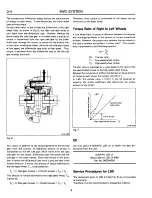
Отзывы: