background image

1

/11.2015/

raisedfloor

1

2

3

4

T

T + 20

B

B + 20

Baugröße

1

2

B

mm

600

1000

T

mm

575

782

-

mm

-

-

Stützen

Stk

4

Rechteckprofile 70 x 40

Stk

4

Mafundstreifen

Stk

4

Schrauben M8 x 30

Stk

8

EN

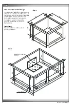
12.4 Raised floor stand

The floor stand is used to adjust the height of the A/C unit to the existing raised floor and consists of an encircling 
rectangular profile of galvanized steel with adjustable screw sockets. Anti vibration compound is recommended bet-
ween concrete floor and base plate.

Locating the supports
(correspondingly on 
the other side)

Cabinet size

B

mm

mm

mm

Supports

Rectangular profiles 70 x 40

Mafund strips

Screws M8 x 30

Cabinet size:

Содержание Mini-Space DX CCD131A

Страница 1: ...IT Cooling Solutions Index G20 Issue 1 2017 Mini Space DX Precision Air Conditioning Units 380 415 3 50 Original instructions...

Страница 2: ...oning 14 6 2 Opening the A C unit 15 6 3 Connection of the piping 15 6 3 1 Refrigerant piping A units 15 6 3 1 1 Design 15 6 3 1 2 Position of the refrigerant connections 16 6 3 1 3 Filling the refrig...

Страница 3: ...the unit and observe the conditions of the power supply companies Switch off the voltage from the unit when working on it Observe the national regulations of the country where the unit will be install...

Страница 4: ...78 part 1 4 Independent of the design the equipment and inspection before the delivery also the operator of such plants has duties according to EN 378 and national regulations This concerns the instal...

Страница 5: ...afety note In the lower part of the unit refrigerant piping Defective filling line for refrigerant leaks in the refrigerant piping closed stop valves defective safety valve Discharge of refrigerant un...

Страница 6: ...glasses and gloves don t put your head into the unit Pressure lines compressor reheat behind heat ex changer Heat Burns in case of contact to the skin Wear safety gloves Avoid contact to hot unit part...

Страница 7: ...truction of protective covering from inside to outside 1 Neopolene cushioning 2 Shrink film 3 Additional board in container shipments 3 2 Transport The Stulz A C units can be moved by lifting devices...

Страница 8: ...rcuits Cooling system A air cooled G water glycol cooled Page code Date of issue month year Page code DE German EN English FR French ES Spanish PL Polish IT Italian PT Portuguese 4 Description 4 1 Typ...

Страница 9: ...by compressor operation in the refrigerant circuit The A C unit control is effected by the on board I O controller The operational conception is designed such as to allow to control up to 19 units fro...

Страница 10: ...N PE 460V 3Ph 60Hz PE Other voltages on request Voltage frequency tolerances as for 400V 3Ph 50Hz The cooling capacity air flow water flow pressure loss sound pressure level and valve sizes change wi...

Страница 11: ...ation temperature 400V 3ph 50Hz 20 Pa 50 Pa 24 C 50 rel humidity Water 30 ethylen glycol 30 C 40 C 45 C The sound pressure levels are valid at a height of 1m and distance of 1m in front of the unit un...

Страница 12: ...3 49 3 49 3 57 1 57 7 57 7 57 7 60 2 Gewicht A kg 136 138 141 141 151 276 279 282 Gewicht G kg 145 147 150 150 160 283 286 289 Upflow Schalldruckpegel 1 m Freifeld dBA 52 0 52 0 52 0 59 5 60 1 59 4 5...

Страница 13: ...07 2016 G20 13 EN 5 3 Dimensional drawings Cabinet size 1 Cabinet size 2...

Страница 14: ...ren unauthorized persons and animals may not have access to the installation site of the A C unit Vibrations emanate from the A C unit due to compressor operation To avoid such vibrations install the...

Страница 15: ...ove the front panel in front of the air section first open the electrical compartment door using the male triangular wrench provided All maintenance measures can be performed from the open front of th...

Страница 16: ...ions Refrigerant line connection The refrigerant connections are located near the compressor and are la belled by the inscriptions pressure pipe and liquid pipe The lines to be connected have to be so...

Страница 17: ...1 151 A EN Refrigerant line connection The refrigerant connections are located near the compressor and are la belled by the inscriptions pressure pipe and liquid pipe The lines to be connected have to...

Страница 18: ...ons are located near the compressor and are la belled by the inscriptions pressure pipe and liquid pipe The lines to be connected have to be soldered Section A A Rear view Front view In general the pi...

Страница 19: ...ion The refrigerant connections are located near the compressor and are la belled by the inscriptions pressure pipe and liquid pipe The lines to be connected have to be soldered Section A A Rear view...

Страница 20: ...which is above the suction pressure of the system This pro cess can be accelerated if the bottle is wrapped in hot moist towels or it is placed in a water bath at a maximum temperature of 50 C Never h...

Страница 21: ...lowing quantities of ethylenglycol indicated as percentage of weight of the water quantity water or outside air temperature ethylenglycol from 5 to 5 C 10 from 5 to 10 C 20 from 10 to 15 C 28 from 15...

Страница 22: ...ection to the external pipes and screw the lines of the external system to the lines of the unit respecting the designation at the unit If any seals are missing these must only be replaced by glycol r...

Страница 23: ...76 76 76 Iy Oy Ix Oz Ox Iz 32 187 46 144 46 85 32 x z y Downflow Upflow CCD U 51 71 91 131 151 G EN To connect the piping notice the labels on the pipe ends Water pipe diameters Rear view Rear view S...

Страница 24: ...50 4 x 32 A A Downflow Upflow CCD U 181 221 251 G EN To connect the piping notice the labels on the pipe ends Water pipe diameters Rear view Rear view Section A A All dimensions in mm Unit Inlet pipe...

Страница 25: ...the pressure in the suction area of the A C unit which prevents the draining of the condensate water Connect the condensate water drains to the local waste water system Comply with the regulations of...

Страница 26: ...ly corresponds to the indications on the rating plate and that the tolerances according to the Application limits are not exceeded In addition to this the asymmetry of phase between the conductors may...

Страница 27: ...rical compartment door of the unit using the key provided Check whether all power switches and control circuit fuses in the electrical section of the unit are switched off Retighten all screw connecti...

Страница 28: ...ch non calibrated range Controller C7000 Start stop key Adjust the desired return air temperature at the controller Start the A C unit by pressing the Start Stop key on the controller Check after 20 m...

Страница 29: ...ome verifications must be effected with the unit in operation measuring the current pressures temperatu res In such a case the unit must only be switched on at the master switch after all mechanical c...

Страница 30: ...r drier fill with R407C according to weight see technical data R407C must be charged in a liquid state in order that the composition of the refrigerant does not change Quantity Check the HP switch An...

Страница 31: ...at exchanger Beyond that the heat exchanger is exposed to the air pollution the particles of which settle at the fins and reduce the heat transmission the same as raise the air resistance The latter s...

Страница 32: ...compressor If this difference exceeds 7 K the condenser is probably polluted In this case the condenser has to be cleaned chemically 8 6 Unit in general Electrics Check the connection terminals for t...

Страница 33: ...alve defective 6 Solenoid valve in liquid line defective Modify setting Refill refrigerant Check connection and cable Check setting of low pressure switch Exchange expansion valve Check electric alime...

Страница 34: ...the oil manufacturer Disconnect the depressurized refrigerant pipes from the external system version A If glycol or similar additives had been used this liquid also has to be collected and disposed in...

Страница 35: ...by us fulfil the requirements of the harmonised EC directives and EC safety standards listed below In the case of a modification of the equipment not co ordinated with us this declaration loses its v...

Страница 36: ......

Страница 37: ...ue to lowering of the water level e g because of the evaporation process or drainage the inlet valve opens until the required capacity is available again If the required steam capacity is lower than t...

Страница 38: ...opened immediately after having produced steam there is danger of burning when touching the steam cylinder Prevention Before carrying out any work set the steam humidifier OEM2 out of operation as des...

Страница 39: ...H3 Green LED Steam production JP1 Jumper block 1 JP2 Jumper block 2 S1 Rotary switch unit type S2 Drain Info key Sx Potentiometer power limitation rH Potentiometer humidity value Y1 Main contactor he...

Страница 40: ...ater conductivity 125 S cm Normal water conductivity 125 S cm DSP Exchangeable steam cylinder Cleanable steam cylinder K Fault No 4 steam cylinder maintenance due the unit triggers a warning only the...

Страница 41: ...nstallation of an Aqua stop valve in the water supply of the humidifier In ad dition to this the room in which the A C unit with the humidifier is installed should be equipped with a water detection s...

Страница 42: ...interval indicates the number of the error see chapter 12 1 4 4 3 Warning and info indication yellow LED in normal operating mode The LED blinks if manual draining is in progress The LED lights if the...

Страница 43: ...w hours of operation that the maximum steam output is not achieved This is normal As soon as the water reaches adequate conductivity through the vaporization process the steam humidifier will work at...

Страница 44: ...ently info mode The amount of blinks per interval indicates the type of malfunction Yellow LED Warning blinks intermittently A malfunction is present The control unit checks whether there is a tempora...

Страница 45: ...more than 72 hours Interval for steam cylinder service exceeded Mineral deposits and or electrodes spent Replace steam cylinder type A clean steam cylinder type D see chapter 5 humidifier service manu...

Страница 46: ...stulz com in the e Stulz area under Downloads Precision A C as a pdf document Here you can only see a diagram which shows the average life cycle of a steam cylinder in dependance of the runtime and th...

Страница 47: ...via an electrically actuated HW valve The HW valve is controlled via the controller The control parameters are adjusted in the operate compo nents heating HWR valve menu on the controller Refer to the...

Страница 48: ...e external hot water circuit The pipelines are to be routed out of the A C unit The diameters for the connection piping of the HW reheat are listed in the following table Malfunction causes Alarm Rehe...

Страница 49: ...The condensate pump is delivered lose The type of pump depends on the A C unit equipment without steam humidifier condensate pump type AB 1 F M March with steam humidifier condensate pump type A2 SA M...

Страница 50: ...it bottom and a grille with horizontal fins in the lower section of the front The fins can be manually adjusted so that the discharge angle of the supply air can be influenced Air discharge to the fro...

Страница 51: ...C D E H Baugr e 1 572 600 425 525 325 500 Baugr e 2 782 1000 625 825 425 500 EN Air discharge plenum Upflow Dimensions The air discharge plenum is set on the A C unit without being screwed CCU Constru...

Страница 52: ...t base is designed for downflow units which are installed in rooms without a raised floor and serves for the discharge of the supply Installation Please note that the unit base has to be bolted to the...

Страница 53: ...5 31 5 38 5 400 400 523 47 564 56 1 EN Base for duct connection and air damper Upflow The base is set on the A C unit without being screwed The duct is fixed on the base with 4 M8 screws 4xM8 nut set...

Страница 54: ...provided on the discharge side for downflow and upflow units The most frequent use of the air damper is shown on the discharge side of upflow units For the installation of an air damper on the upflow...

Страница 55: ...7 01 2017 air_MSDX 60 80 220 EN Adaptor plate for damper below the unit Downflow Top view Front side Top view Front side Size 2 Size 1...

Страница 56: ...ide Bottom view Front side Air damper Downflow Here the use of the air damper on the discharge side of downflow units is shown For the installation of an air damper below the downflow unit an adaptor...

Страница 57: ...ilter top with flexible duct is determined for the suction side connection at downflow units Installation Fix the flexible duct on the filter top by four M10 screw connections Set the filter top with...

Страница 58: ...10 01 2017 air_MSDX 150 1000 810 700 160 920 EN Size 2 Filter top with flexible duct...

Страница 59: ...SR for fresh or return air The louver actuator has no end position switch and is overload proof When the limit stop of the louver is attained the actuator automatically stops After switching on the po...

Страница 60: ...12 01 2017 air_MSDX 104 375 104 583 600 583 81 376 110 642 376 63 250 63 1311 1876 1986 300 507 EN Dimensions Size 1 Downflow with Ecocool louvers front side rear side Outside air Return air...

Страница 61: ...air_MSDX 117 852 89 583 876 583 1184 1874 1994 104 125 125 125 104 1000 876 63 125 125 125 125 125 125 63 507 800 EN Dimensions Size 2 Downflow with Ecocool louvers rear side front side Outside air R...

Страница 62: ......

Страница 63: ...s used to adjust the height of the A C unit to the existing raised floor and consists of an encircling rectangular profile of galvanized steel with adjustable screw sockets Anti vibration compound is...

Страница 64: ...y damping insertions and that mafund plates are laid under the floor supports The raised floor cutting notch should at least be 15 and must not have any contact to the raised floor stand which could r...

Страница 65: ...r shafts are connected by a coupling piece The louver actuator which has to be installed on the shaft will later be on the right unit side in the proximity of the electric cabinet Positioning of the A...

Страница 66: ......

Страница 67: ...e Phase Control The phase monitoring relay monitors a phase failure and a phase reversal Excess voltage undervoltage and the phase imbalance are monitored in relation to the set values In case of a ph...

Страница 68: ...d 13 Colour RAL 7035 4 mounting holes for wall mounting All three phases of both power supplies are checked constantly on under voltage phase failure phase balance and correct rotation In case of fail...

Страница 69: ...75 C Install two back up fuses in the supply lines The size of the back up fuses depends on the terminal equipment A C unit Choose the cable cross sections in accordance with local standards the layi...

Страница 70: ......

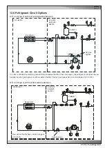
Страница 71: ...e refrigerant circuit can be en hanced by a hot gas bypass or with a suction throttle The hot gas bypass has a control range of 50 to 100 Evaporator Fan Hot gas bypass Low tem perature section Air sec...

Страница 72: ...he controller of your A C unit Permanently set high pressure and low pressure switches are required as sensors for this An adjustable version of these HP LP switches is supplied in order to individual...

Страница 73: ......

Страница 74: ...045 633 16 35 info stulz it IN STULZ CHSPL INDIA PVT LTD 006 Jagruti Industrial Estate Mogul Lane Mahim Mumbai 400 016 Tel 91 22 56 66 94 46 Fax 91 22 56 66 94 48 info stulz in NL STULZ GROEP B V Post...

Отзывы: