IMPORTANT
File in your
maintenance
records
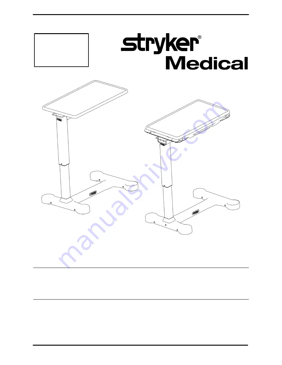
COMPANION(SINGLE TOP TABLE)
COMPANION II(SPLIT TOP TABLE)
Companion & Companion IIOverbed Tables
OPERATIONS AND MAINTENANCE MANUAL
For Parts or Technical Assistance1-800-327-0770
Страница 1: ... File in your maintenance records COMPANION SINGLE TOP TABLE COMPANION II SPLIT TOP TABLE Companion Companion II Overbed Tables OPERATIONS AND MAINTENANCE MANUAL For Parts or Technical Assistance 1 800 327 0770 ...
Страница 2: ...oughly CAUTION Quaternary Germicidal Disinfectants used as directed and or Chlorine Bleach products typically 5 25 So dium Hypochlorite in dilutions ranging between 1 part bleach to 100 parts water and 2 parts bleach to 100 parts water are not considered mild detergents THESE PRODUCTS ARE CORROSIVE IN NATURE AND MAY CAUSE DAMAGE TO YOUR EQUIPMENT IF USED IMPROPERLY If these types of products are u...
Страница 3: ... 2 To unlock and lower the table top grasp handle A and pull it upward while guiding the table top down 3 Pull out vanity B with flip up mirror in either direction optional NOTE It is possible to raise the table top without using the handle For normal operation however the recommended method is to use the handle while raising the table top ...
Страница 4: ... table top grasp handle A and pull it upward while guiding the table top down 3 Lift B to release secondary tray in either direction 4 Pull out vanity C with flip up mirror in either direction optional NOTE It is possible to raise the table top without using the handle For normal operation however the recommended method is to use the handle while raising the table top ...
Страница 5: ...ase Frame Weldment 1 B 3100 52 734 Caster 4 C 16 41 Kep Nut 16 D 3 123 Hex Washer Hd Screw 16 Assembly Method 1 0 Place the base frame weldment A upside down on the assembly surface 1 5 Place a caster B on the base frame Insert the four hex washer head screws D from the top of the base frame Thread the four kep nuts C onto the four bolts and tighten them securely Repeat on the remaining three cast...
Страница 6: ...0 105 Single Top Gas Spring 1 C 52 713 Hose Clamp 1 D 3100 100 023 Conical Bushing 1 E 3100 100 024 Lock Bushing 1 F 3100 100 013 Spring 1 G 3100 100 025 Spring Retainer 1 H 3100 100 026 Release Hoop 1 J 3100 100 036 Lower T Handle 1 K 3100 100 027 Release Rod 1 L 21 143 Set Screw 2 Apply Loctite 242 thread lock adhesive Note If table will not lower see page 8 for adjustment procedure ...
Страница 7: ...y into the spring retainer release hoop assembly 7 0 Insert item E lock bushing into the spring retainer release hoop assembly and over the gas cylinder shaft Locate the ledge on item E over the end of item H without the through hole The surface with the angular ramp should face down as shown on page 5 Insert item F spring on top of item E and over the gas cylinder shaft slightly compressing item ...
Страница 8: ...evis Pin 1 M 3100 100 063 Outer Shim 030 1 D 27 19 Cotter Pin 2 3100 100 065 Outer Shim 040 1 E 34 267 Nylon Flanged Bushing 1 3100 100 066 Outer Shim 050 1 F 52 801 Nyliner Sleeve 2 N 3100 100 069 Inner Shim 030 1 G 3100 100 012 Bellow 1 3100 100 067 Inner Shim 040 1 H 3100 100 017 Inner Tube Frict Grommet 1 3100 100 068 Inner Shim 050 1 J 3100 100 020 Inner Column Weldment 1 P 3100 100 1 10 Lift...
Страница 9: ...em R with the cylinder shaft end first Align the T handle with the holes in item J inner column Insert item B clevis pin through both column walls and the T handle Fasten item D cotter pin through the slot on item B clevis pin Extend item R outer column and properly align the column through holes with the T handle Insert item C clevis pin through both column walls and the T handle Fasten item D co...
Страница 10: ...n Table Top Assembly Assembly part number 3100 100 54 Edgemold 3100 100 43 T Band Assembly part number Item Part No Part Name Qty A 3100 100 14 Wood Insert 6 B 3100 100 45 T Band Top 1 3100 100 50 Edgemold Top 1 ...
Страница 11: ...100 205 Split Top Gas Spring 1 C 52 713 Hose Clamp 1 D 3100 100 023 Conical Bushing 1 E 3100 100 024 Lock Bushing 1 F 3100 100 013 Spring 1 G 3100 100 025 Spring Retainer 1 H 3100 100 026 Release Hoop 1 J 3100 100 036 Lower T Handle 1 K 3100 100 027 Release Rod 1 L 21 143 Set Screw 2 Apply Loctite 242 thread lock adhesive Note If table will not lower see page 8 for adjustment procedure ...
Страница 12: ...e spring retainer release hoop assembly 7 0 Insert item E lock bushing into the spring retainer release hoop assembly and over the gas cylinder shaft Locate the ledge on item E over the end of item H without the through hole The surface with the angular ramp should face down as shown on page 10 Insert item F spring on top of item E and over the gas cylinder shaft slightly compressing item F under ...
Страница 13: ...ylock Hex Nut 1 C 3100 100 012 Bellows 1 M 52 801 Nyliner Sleeve 2 D 3100 100 020 Inner Column Weldment 1 N 34 267 Nylon Flanged Bushing 1 E 3100 100 017 Inner Tube Frict Grommet 1 P 3100 100 065 Outer Shim 040 1 F 26 262 Clevis Pin 1 3100 100 066 Outer Shim 050 1 G 27 19 Hair Pin Wire 2 Q 3100 100 067 Inner Shim 040 1 H 3100 100 210 Gas Spring Assembly 1 3100 100 068 Inner Shim 050 1 J 26 263 Cle...
Страница 14: ...lift lock assembly single top into item A with the cylinder shaft end first Align the T handle with the holes in item D inner column Insert item F clevis pin through both column walls and the T handle Fasten item G cotter pin through the slot on item F clevis pin Extend item A outer column and properly align the column through holes with the T handle Insert item J clevis pin through both column wa...
Страница 15: ...100 085 Split Top Release Handle 1 D 3100 100 078 Gear Rack 2 E 23 69 Pan Hd Sheet Metal Screw 6 F 3100 100 090 Slide with Clinch Nut 2 G 3100 101 010 Split Top Vanity Assembly 1 H 23 306 Pan Hd Sheet Metal Screw 8 J 3100 100 079 Gear 2 K 3100 100 080 Secondary Tray 1 L 3100 100 095 Split Top Weldment 1 M 7 66 Phillips Truss Hd Screw 4 N 14 67 Flat Washer 4 ...
Страница 16: ...15 Companion II with T Band Assembly Detail A Assembly part number 3100 100 048 M M L ...
Страница 17: ...tem A without item C NOTE The gear teeth on item D gear rack are facing toward the center of item A Verify the paddles on item C are facing toward the outside edges of item A refer to the drawing on page 14 2 5 Spray silicon lubricant on the track surface of each item D gear rack Wipe off excess lubricant 3 0 Slide item K secondary tray onto the tracks on item D so the molded gear racks are visibl...
Страница 18: ...100 100 085 Split Top Release Handle 1 D 3100 100 078 Gear Rack 2 E 23 69 Pan Hd Sheet Metal Screw 4 F 3100 100 090 Slide with Clinch Nut 2 G 3100 101 010 Split Top Vanity Assembly 1 H 23 306 Pan Hd Sheet Metal Screw 8 J 3100 100 079 Gear 2 K 3100 100 080 Secondary Tray 1 L 3100 100 095 Split Top Weldment 1 M 7 66 Truss Hd Torx Screw 4 N 14 67 Flat Washer 4 ...
Страница 19: ...18 Companion II with Edgemold Assembly Assembly part number 3100 100 070 Detail A L M M ...
Страница 20: ...her end of item A without item C NOTE The gear teeth on item D gear rack are facing toward the center of item A Verify the paddles on item C are facing toward the outside edges of item A see the drawing on page 17 2 5 Spray silicon lubricant on the track surface of each item D gear rack Wipe off excess lubricant 3 0 Slide item K secondary tray onto the tracks on item D so the molded gear racks are...
Страница 21: ...tem K column assembly through the opening in item E cover as shown 1 3 Attach item K column to the base frame as shown using a 3 16 Allen wrench and 3 item B truss head torx screws 1 4 Attach item C clip nut through the square opening in item F base weldment 1 5 Push the bottom flange of the bellows through the opening in item E cover 1 6 Place item E cover over the base 1 7 Attach item E cover us...
Страница 22: ...lip Nut 8 D 23 92 Truss Hd Screw 8 E 3100 100 005 Cover Assembly 1 F 3100 100 010 Base Weldment Assembly 1 G 3100 100 043 T Banded Single Top Ass y 1 3100 100 054 Edge Molded Single Top Ass y 1 H 3100 100 098 Date Code Label 1 J 3100 100 099 Labels Set of 4 1 K 3100 100 241 Single Top Column Ass y 1 L 8808 041 000 Lift Label 1 ...
Страница 23: ...column assembly through the opening in item A cover as shown 1 3 Attach item B column to the base frame as shown using a 3 16 Allen wrench and 3 item C truss head torx screw 1 4 Attach item J push nut through the square opening in item E base weldment 1 5 Push the bottom flange of the bellows through the opening in item A cover 1 6 Place item A cover over the base 1 7 Attach item A cover using 8 i...
Страница 24: ...crew 3 D 23 92 Truss Hd Screw 8 E 3100 100 010 Base Weldment Assembly 1 F 3100 100 048 T Banded Split Top Ass y 1 3100 100 070 Edge Mold Split Top Ass y 1 G 4 292 Button Hd Hex Soc Screw 2 H 3100 100 061 Outer Mounting Plate 1 J 18 36 Plastic Clip Nut 8 K 3100 100 099 Labels Set of 4 1 L 3100 100 098 Date Code Label 1 M 8808 041 000 Lift Label 1 ...
Страница 25: ... Name Qty A 3100 100 003 Single Top Vanity Track 2 B 23 256 Pan Hd Sht Metal Screw 8 C 3100 101 010 Vanity Tray Assembly 1 D 3100 100 051 Bumper 2 OPTIONAL ACCESSORY ASSEMBLY OF VANITY TO SINGLE TOP COMPANION TABLE Kit Part Number 3100 101 005 ...
Страница 26: ... the maintenance manual for each device This statement constitutes Stryker s entire warranty with respect to the aforesaid equipment STRYKER MAKES NO OTHER WARRANTY OR REPRESENTATION EITHER EXPRESSED OR IMPLIED EXCEPT AS SET FORTH HEREIN THERE IS NO WARRANTY OF MERCHANTABILITY AND THERE ARE NO WARRANTIES OF FITNESS FOR ANY PARTICULAR PURPOSE IN NO EVENT SHALL STRYKER BE LIABLE HEREUNDER FOR INCIDE...
Страница 27: ... without approval from the Stryker Customer Service Department An autho rization number will be provided which must be printed on the returned merchandise Stryker reserves the right to charge shipping and restocking fees on returned items SPECIAL MODIFIED OR DISCONTINUED ITEMS NOT SUBJECT TO RETURN Damaged Merchandise ICC Regulations require that claims for damaged merchandise must be made with th...
Страница 28: ...0 90 101 REV C European Representative Stryker France Phone 33148632290 BP 50040 95946 Roissy Ch de Gaulle Fax 33148632175 Cedex France 6300 Sprinkle Road Kalamazoo MI 49001 9799 800 327 0770 www strykermedical com ...