background image

TABLE OF CONTENTS 

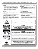
OVERVIEW / NSF® TYPE / COMPLIANCE / WARNINGS / PRECAUTIONS / WIRING………………. 

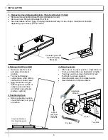
INSTALLATION …………………………………………………………………………………………..…….. 

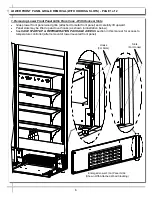
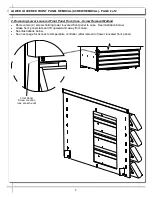
LOWER FRONT PANEL GRILLE REMOVAL (WITH HOOKS & SLOTS) ………………………….….. 

LOWER LOUVERED FRONT PANEL REMOVAL (SCREW REMOVAL) …………………………….... 


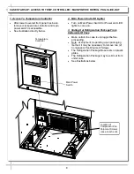
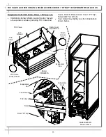
CASE START-UP: ACCESS TO TEMP. CONTROLLER / MAIN POWER / REFRIGERATION 


PACKAGE SLIDE-OUT ………………………………….……...………………....…………….…... 

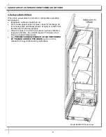
CASE START-UP: HONEYCOMB AIR DIFFUSER DISCHARGE ……………………………………….. 


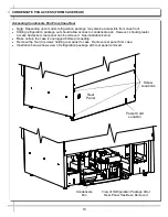
CONDENSATE PAN ACCESS (FROM CASE REAR) ……………………………………………………. 


TXV VALVE & COVER / DRAIN & DRAIN ACCESS COVER / “P-TRAP” / EVAPORATOR  


FAN & COILS ………………………………………………………………………………………….. 


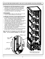
LED LIGHT FIXTURES: ROCKER SWITCH / LED LIGHT ‘TOUCH SENSOR’ LOCATION AND 


OPERATION ..………………………………………………………………………………………….. 

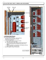
LED LIGHT FIXTURES:  REMOVAL AND REPLACEMENT ..………...…………………………………. 

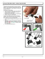
LED LIGHT FIXTURES, CONT’D: ‘PLUG-IN’ INSTRUCTIONS …………………………………………. 


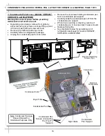
CONDENSATE PAN ACCESS / REFRIGERATION PACKAGE LAYOUT FOR CDR4287, 


CDR4287A AND B427WND …...…………………………………………………………………….. 

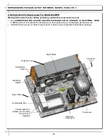
REFRIGERATION PACKAGE LAYOUT FOR MODEL B428WN ….…………………………………….. 

REFRIGERATION PACKAGE LAYOUT & ACCESS FOR MODEL B427WN ………………………..... 


CLEANING SCHEDULE - TO BE PERFORMED BY STORE PERSONNEL …….…………………….. 


PREVENTIVE MAINTENANCE (PERFORMED BY TRAINED SERVICE PROVIDER) ……..………... 


TROUBLESHOOTING - GENERAL ISSUES …….………………….…………….……….…...…………. 

TROUBLESHOOTING - CONDENSING SYSTEM …..……………..…………….……….……………….. 

TROUBLESHOOTING - EVAPORATOR SYSTEM …..…………..……………….……….………………. 


SERIAL LABEL INFORMATION & LOCATION …………………………………………………………... 


CAREL® CONTROLLER - PROGRAMMING THE INSTRUMENT ..…………………………….…….... 

CAREL® CONTROLLER - USER INTERFACE, SUMMARY TABLES OF ALARMS & SIGNALS … 

CAREL® CONTROLLER - Summary Table of Operating Parameters (After Programming Key) .. 


TECHNICAL SERVICE CONTACT INFORMATION & WARRANTY INFORMATION ..………………. 

3-4 


10 


11 


12 

13 

14 


15 

16 

17 


18 


19-20 


21-22 

23 

24 


25 


26 

27 

28 


29 

Models Represented In This Manual* 


W3R / W4R / CDR4287 /  CDR4287A / B427WN / B427WND / B427WNDD / B428WN 

* This Manual May Cover Additional Models That May Not Be Listed Above. 

Содержание Oasis B427WN

Страница 1: ...m Model W3R CDR4287 Refrigerated Wine Units INSTALLATION AND OPERATING MANUAL Model W4R Refrigerated Wine Unit Refrigerated Wine Units Model CDR4287A Left Adjoined To Model B428WN Right Model B427WN R...

Страница 2: ...R4287 CDR4287A AND B427WND REFRIGERATION PACKAGE LAYOUT FOR MODEL B428WN REFRIGERATION PACKAGE LAYOUT ACCESS FOR MODEL B427WN CLEANING SCHEDULE TO BE PERFORMED BY STORE PERSONNEL PREVENTIVE MAINTENANC...

Страница 3: ...gs to prevent injury or death Please read carefully REFRIGERANT DISCLOSURE STATEMENT This equipment is prohibited from use in California with any refrigerants on the List of Prohibited Substances for...

Страница 4: ...ust be replaced with similarly treated lamps CAUTION PRECAUTIONS This sheet contains important precautions to prevent damage to unit or merchandise Please read carefully See previous page for specific...

Страница 5: ...proper position To prevent damage support case while sliding skid out from under case Note Illustration at right reflects general outline of sample case and does not reflect any particular model or op...

Страница 6: ...to metal front panel and carefully lift upward Panel slots may be lifted up and over hooks as shown in illustration below See CASE START UP REFRIGERATION PACKAGE ACCESS section in this manual for acce...

Страница 7: ...moval Method Remove two 2 screws holding lower louvered front panel to case See illustration below Grasp front panel slats and lift upward and away from case See illustrations below See next page for...

Страница 8: ...h for Power and LED lights to come on 3 Sliding Out Refrigeration Package From Underside Of Case Make certain the case is unplugged before proceeding Note At shipment depending upon packaging method i...

Страница 9: ...eck for discharge air from honeycomb air diffuser shown at right to confirm that the fans are functioning properly When the case is in a start up mode or has been idle for a long period of time the un...

Страница 10: ...e pan However should greater access be desired rear panel can be removed See illustration below Make certain the case is unplugged before proceeding Remove the four 4 screws holding rear panel to case...

Страница 11: ...coil area including TXV Valve and Cover Drain Drain Access Cover P Trap Evaporator Fan Coils Your model may slightly vary from illustrations shown below TXV Valve Drain Evaporator Fan Model CDR4287A D...

Страница 12: ...tening by touch This one Touch Sensor controls all LED lights LED lights come on when Main Power has been turned on Touch the LED Touch Sensor LED lights will turn off Touch it again and LED lights wi...

Страница 13: ...switch To remove faulty LED light follow these steps A Disconnect plug from LED light B Using both hands grasp LED light assembly with its mag netic mounting clips Pull downward and off its shelf or h...

Страница 14: ...erly in shelf header Note If mounting clips are riveted to shelf or header attach by placing LED in base of clip and then snapping into clip at FLANGE SIDE Press plug s barrel shaped insert deep into...

Страница 15: ...nt retaining screws Carefully slide out refrigeration package Unplug the condensate pan from its outlet Condenser Coils Compressor Dryer Filter Condenser Fan Sight Glass Electrical Components Note Con...

Страница 16: ...KAGE LAYOUT CDR4287 A B427WND PAGE 1 OF 3 section in this manual for instructions on front grille removal condensate pan access etc Illustration below may not reflect every feature or option of your p...

Страница 17: ...ine Coil Compressor Electrical Box Hot Gas Condensate Overflow Electrical Coil 3 Refrigeration Package Layout For Model B427WN Warning Disconnect power before providing maintenance and service to unit...

Страница 18: ...e from case Submerse in warm soapy water Use soft bristled brush to remove dust grease and grime that collects on filter Rinse thoroughly After filter has dried return to case See CONDENSATE PAN ACCES...

Страница 19: ...se Replace rear grille to case using either hooks or screws Weekly Condenser Coil Remove Front Grille See CASE STARTUP REFRIGERATION PACKAGE ACCESS section for instructions on removing Front Grille Va...

Страница 20: ...it to be pulled out of honeycomb retainer C Carefully pry downward and away from the honeycomb retainer A B C D E F Clean honeycomb with warm water and soap solution Submerse if necessary Use brush t...

Страница 21: ...ades are securely mounted to fan motor Check that nothing is preventing blade rotation Check that the fan shroud is properly secured Fans Are Not Working Check that the MAIN power switch is on Check t...

Страница 22: ...e amount of warm product was added to the case it will take time for the temperature to adjust Temperature changes during defrost mode but will return to normal Check that the case is not in the sun o...

Страница 23: ...system Check that liquid line filter dryer is not plugged Check that close offs are intact around condensing coil and that air is not recirculating Check that store ambient temperature isn t above max...

Страница 24: ...coil is not iced up High Suction Pressure Check for refrigerant overcharge Check that compressor reed valves aren t bad Look for high suction low head pressure Perform pump down Check that the cooling...

Страница 25: ...erature refrigeration information as well as regulatory standards to which the case conforms For additional technical information and service see the TECHNICAL SERVICE page in this manual for instruct...

Страница 26: ...s timeout occur normal operational settings prior to modifications being made will resume 3 If the instrument is switched off before pressing the Prg key all modifications to parameters will be lost S...

Страница 27: ...set reset HACCP alarms reset temp monitoring Summary Table of Alarm and Signals Display Buzzer and Relay Integrated Electronic Microprocessor Controller Read And Save These Instructions Page 2 of 3 Us...

Страница 28: ...F 50 200 dP1 Maximum defrost duration evaporator min F 1 250 d6 Display on hold during defrost C 0 2 dd Dripping time after defrost min F 0 15 d 1 Display of defrost probe 1 C F F 28 For Case Specifi...

Страница 29: ...onable attorney fees and costs Remedies of SCC SCC s rights and remedies shall be cumulative and may be exercised from time to time In a proceeding or action relating to the breach of this Agreement b...

Отзывы: