


Page 11 of 16
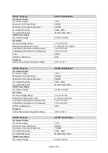
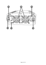
Reference
Subassembly
1
Ventilation Opening
2
Cooling Fan
3
Remote Switch Port
4
USB Port
5
Digital Display
6
Power Switch Button
7
Output Power Indicator (W)
8
AC Outlet
9
AC Outlet Overload Reset Circuit
10
Input Indicator (V)
11
Output Power Indicator (kW)
12
Positive DC Terminal
13
Ground Terminal
14
Negative DC Terminal
15
Terminal Covers
16
Cooling Fans
17
DC Cable
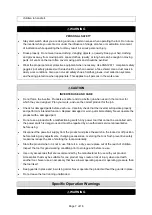
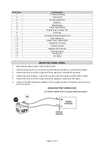
Assembly Instructions
1.
Make sure the power switch on the inverter is OFF.
2.
Connect the red positive (+) end of the ring terminal to the positive (+) terminal of the battery.
3.
Connect the other end of the ring terminal to the positive (+) terminal of the inverter.
4.
Connect the black negative (-) end of the ring terminal to the negative terminal of the inverter.
5.
Connect the other end of the ring terminal to the negative (-) terminal of the battery.
6.
Connect a
14AWG stranded insulated wire to the inverter ground terminal and connect the other
end to the ground.
Содержание 53067
Страница 10: ...Page 10 of 16 17 ...