THE STRONG SWITCHING POWER SUPPLY also includes Phase Loss Detection and
Brown-Out Protection which will disable the power supply in the event of problems in the AC supply line. See
the power supply Instruction Manual for detailed information.
ELAPSED HOURS will begin counting upon bulb ignition. Bulb hours (BLB) are limited to
four digits, and are re-set when the xenon bulb is replaced. To re-set bulb hours, press the RESET button
accessible through marked hole below the LCD screen. The 5/64" allen wrench used to tighten the front bulb
collar set screw is the correct diameter to clear the hole. NOTE: when recording start-up and removal hours on
the Xenon Bulb Record, use the total elapsed hours (HR) figures. The (BLB) figure, re-set upon installation of
the bulb, is a convenience feature ONLY. Basing records of the lamp system on the total hours (HR) figures
permits an accurate and ongoing history of bulb usage.
IF THE XENON BULB fails to ignite after several igniter pulses, additional diagnostic mes-
sages will display on the LCD screen:
CHECK PWR SUPPLY:
If no DC current is sensed, and voltage does not exceed 125 V.DC, check the xenon
power supply. Repair or replace as required.
CHECK IGNITER:
If the DC open circuit voltage reaches and exceeds 140 V.DC and the igniter fails to
pulse, replace the igniter.
DIAGNOSTIC MESSAGES serve as prompts and suggestions but do not replace traditional
troubleshooting procedures. If an access door is closed and secured but transmits an error message, check the
subject door interlock switch with an ohmmeter and replace if defective. Dirt or dust fouling an air vane switch
will cause a “blower” error message. A “power supply” or “igniter” error message might be caused by a loose
or oxidized connection.
X90/017
Содержание X-90
Страница 2: ......
Страница 21: ...X 90 LAMPHOUSE SCHEMATIC Analog Controls X90 019 ...
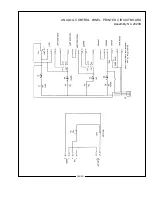
Страница 23: ...ANALOG CONTROL PANEL PRINTED CIRCUIT BOARD Assembly No 23239 X90 021 ...
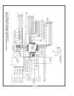
Страница 24: ...X90 022 DIGITAL CONTROL PANEL PRINTED CIRCUIT BOARD Assembly No 23976 Wiring Diagram 1 of 3 ...
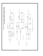
Страница 25: ...X90 023 DIGITAL CONTROL PANEL PRINTED CIRCUIT BOARD Assembly No 23976 Wiring Diagram 2 of 3 ...
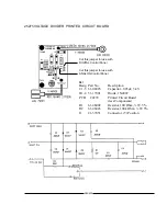
Страница 26: ...X90 024 DIGITAL CONTROL PANEL PRINTED CIRCUIT BOARD Assembly No 23976 Wiring Diagram 3 of 3 ...
Страница 43: ......
Страница 44: ......


