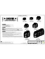


Striem
3100 Brinkerhoff
Kansas City, KS 66115
Tel: 913-222-1500
Fax: 913-291-0457
www.
striemco.com
Made in the U.S.A
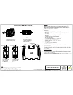
Oil Separator (OS)
Oil Collection Tank (OCT)
FLOW
A
A
INLET
OIL DRAW OFF
OUTLET
Spill Line
COMMON VENT
Maximum Oil Capacity
Operating Water Level
Static Water Level
Adjustable Oil
Draw-Off Arm
Oil Separator (OS)
Oil Collection Tank (OCT)
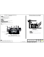
Oil Collection Tank Installation
(OCT-50, OCT-125, OCT-275)
CONNECTIONS
Connect vent pipe and spill line as shown.
1.
Install an additional vent on the outlet pipe of the OS unit.
2.
Adjust Oil Draw-Off arm between 1/4" to 1/2" above operating water line.
3.
INSTALLATION INSTRUCTIONS
Install unit(s) as close as possible to OS Series tank.
1.
OCT tank installation is identical to similar sized OS tanks. See Sheets #2 through #4, and sheets #7
2.
and #8 for TeleGlide installation.
PUMPING FREQUENCY:
Frequency depends on the capacity of the interceptor and the
amount of oil and sediment in the wastewater.
After initial installation, it is recommended that the unit is pumped
every 3 to 4 weeks. Monitor each pumping to establish an adequate
maintenance Striem recommends pumping
frequency not to exceed more than 6 months.
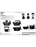
OIL DRAW-OFF (OPTIONAL)
Striem Oil Separators may be ordered with a 1-1/2" draw-off unit consisting
of an adjustable draw-off tube and slip-nut. In order for the Oil Separator to work
properly, the oil draw-off must be adjusted to meet the correct operating
height for the flow of the unit. The oil draw-off unit leads separated oil into an
oil drainage line and collection tank, where it can be taken care of properly
(See OCT Series).
Once the Oil Separator is installed, an operating water level must be established.
Remove covers and run water through separator at maximum flow rate. Move
adjustable draw-off tube between 1/4" to 1/2" above operating water line. If
discharged oil contains water, raise adjustable tube until only oil is being removed.
Draw-off setting must be checked periodically. If draw-off tube is properly set,
water will not draw off with oil.
Slip-nut
Adjustable gravity
draw-off tube
Oil discharge to
collection tank
Exterior wall
of separator
Static water level
Operating water level
OS & OCT SERIES INSTALLATION,
OPERATION AND MAINTENANCE GUIDE
ECO:
8/15/18
MJ
REV:
DATE:
DWG BY:
DESCRIPTION:
PROPRIETARY AND CONFIDENTIAL
THE INFORMATION CONTAINED IN THIS DRAWING IS THE SOLE PROPERTY OF
STRIEM, LLC.
ANY REPRODUCTION IN PART OR AS A WHOLE WITHOUT THE WRITTEN PERMISSION OF
STRIEM, LLC.
IS
PROHIBITED.
NOTES:
Striem oil separators are rated and manufactured with an internal flow control system already in
place. They do not require an external flow control system or air intake vent.
Striem oil separators are not to be installed in any other manner except as shown. Consult local
codes for separate trapping requirements, cleanout locations and additional installation instructions.
SHEET NUMBER:
5 of 7


