background image


20 

2.2.2.5.1 

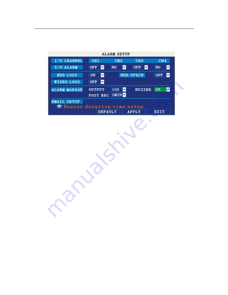
ALARM SETUP 

Move the cursor to

ALARM SETUP

】(

Icon highlighted when selected

),

press

Enter

to enter into setting interface.   


I/O CHANNEL

  Each channel corresponds an I/O status, that is, when an alarm triggered, it will 

activate the corresponding channel to start alarm recording.   

                        N.O

indicate I / O input level from high to low effective 

                        N.C

indicate I / O input level from low to high effective 

HDD LOSS

ON means it will trigger a alarm if there is no HDD, and it will display an 

H


On the bottom left of channel 1 in the live view 

HDD SPACE

ON

If the space less than 500M, there is a remark in live view

No enough space, 

please change HDD after shutdown. 

VIDEO LOSS

ON

when one channel has no video input, it will display “video loss”in live view.   

ALARM MANAGE

There are alarm output, buzzer and post REC three items. 

OUTPUT

when an alarm triggered, the alarm output time will be: 

0 second

10 seconds,20 seconds,40 seconds and 60 seconds 

● 

BUZZER

buzzer calling time setup when alarm triggered: 0 second,10 

seconds,20 seconds,40 seconds and    60 seconds 

● 

POST REC.

post recording time setup: 30 seconds,1 minute,2 minutes and 5 

minutes   

● 

PRE REC

Pre-recording time is fixed as10 seconds. 

2.2.2.5.2 

SYSTEM INFO   

Move the cursor to

SYSTEM INFO

】(

Icon highlighted when selected

),

press

Enter

to 

enter  into  setting  interface,  at  this  interface  mainly  display  system  hardware  features  and 

firmware version, include : device type, software version, MAC address

serial number. 

Содержание 7704

Страница 1: ...H 264 NETWORK Embeded DVR 7704 7708 USER MANUAL CONTENT 1 INTRODUCTION 3 1 1 Main Feature 3 1 2 Product features 3 1 2 1 Parameter 3 ...

Страница 2: ...EM LANGUAGE SETUP 16 2 2 2 4 2 DATA TIME SETUP 16 3 IE OPERATION 27 3 1 FEATURE 27 3 2 USER LOGIN 27 3 3 OPERATION INTERFACE 28 3 3 1 LIVE 28 3 3 1 1 PTZ CONTROL 28 3 3 1 1 1 ZOOM 29 3 3 1 1 2 PTZ PRESET 29 3 3 1 2 PLAY 29 3 3 1 3 OTHER OPERATION 29 3 3 2 REPALY 30 3 3 3 SETUP 32 3 3 3 1 RECORD 32 3 3 3 2 ALARM 33 3 3 3 3 PTZ 34 3 3 3 4 NETWORK 34 3 3 3 5 SETTING 35 3 3 3 6 HOST INFO 36 4 DVR Inst...

Страница 3: ...menu selected optimized four channel simultaneously playback 8ch just support one channel playback double level user management Support the live view parameter setting and copy playback video via network 1 2 1 Parameter Item Device performance index Language Chinese English GUI Graphic menu System password user password administrator password Video in 4ch complex video input 1 0Vp p impedance75Ω B...

Страница 4: ...ure proceeding and store Data storage Alarm input 4 alarm input Alarm Alarm output 1 alarm output Servial interface Support 1 RS232 Servial interface Support 1 RS485 Connector Network interface RJ45 10M 100M Mouse USB1 1 USB Udisk USB2 0 VGA VGA 1 VGA select Software PC playback Playback video file Software upgrade Support USB network firmware upgrade voltage input AC 110 240V Voltage output DC 19...

Страница 5: ... 3 ENTIRONMENT ADAPTABILITY For the saftly using DVR and prolong device life please pay attention on following detail 1 When installing device please comply all the electric product safty criterion 2 Power and ground Do not touch the power and DVR with a wet hand Do not drop liquid on DVR Do not put others on DVR Please using soft dry cloth when clean DVR do not using chymistimpregnant When the po...

Страница 6: ...ontrol has the same function with mouse left click 2 1 Remote key instruction 2 1 1 Remote control Handheld IR Controller Key Functions 0 9 keys During setup number keys are used to input values For viewing channels 1 2 3 and 4 use 1 2 3 and 4 on numeric keypad respectively ...

Страница 7: ...X 4X four modes are available Press REW to switch press PLAY to return to normal speed POWER ON Reset the MDVR to Power on and Power off mode standby and start up LOGIN LOCK If the security is enabled in the setup use LOGIN LOCK key to enter the user setup It is important to remember the password due to without restoration function Log in to enter into User ID select and Password input interface a...

Страница 8: ...ny options in the option frame click left key to ball out down pull menu Click left key To click the left key on the playback interface can make means forward means rew I means Slow play I means frame play means Play X means exit Click left or right key 1 In the input frame click the left key or right key can activate the keyboard Click the right key can make the switch of Chinese and English on t...

Страница 9: ...9 2 1 3 Menu Tree You can control the DVR by a lot of menu operation This tree will show you the menu structure and it will be in details in after chapter ...

Страница 10: ...llow if the password is enabled Input device ID and user password via numeric key board and you access to main menu via press Apply Remark default device ID is 00000 and the password is user password is oooooo and Admin password is 020818 in order to manage the device more convenience please setup the user password and change the device ID in the base setup You can setup user and admin password Ad...

Страница 11: ...to everwhere there will have the explanation information showed autoly 2 2 2 1 RECORD SEARCH Move the cursor to RECORD SEARCH Icon highlighted when selected press Enter to enter into the setting interface RECORD FILE You can adjust the checking date and time press Enter or input the number directly to adjust the year month date After finishing the time setting move the cursor to SEARCH and press A...

Страница 12: ... interface of the selected date LOG SEARCH Enter into the log seaching interface EXIT Exit video search to back to the previous menu 1 FILE LIST Setup the searching date after pressing SERACH move the cursor to FILE LIST and press APPLY to enter into the video file list of this date CHANNEL There is 1 2 3 4 and all channel totally 5 options Press Enter or to select TYPE There are all normal and al...

Страница 13: ...e recording file by direction keys or and press Enter means selected OK There is a at the end of the selected recording files and press Enter again the will disappear that means cancel the select we can start export the recording files after selecting and press BACKUP to start to backup as follow Instruction 1 When the space in backup device less than recording file the system will prompt Space no...

Страница 14: ...ce will start recording when it startup TIME Recording as the schedule you can setup the schedule as you want as follow CHANNEL You can select all channel or just one channel blue means has selected WEEKLY You can select all everyday weekend workday or each day blue means has selected DAILY There are ALARM NORMAL NO REC three modes if you select this that means all the day will record as this mode...

Страница 15: ...mat No HDD If HDD can not run normally including unformat and no HDD there is a H display on video live view OVERWRITE ENABLE means when HDD space less than 4G it will delete HDD earliest recording file and it will stop deleting when the space is 10G DISABLE means when HDD space less than 500M it will stop recording and an prompt will display in live view please shutdown and replace HDD FORMAT Mov...

Страница 16: ...e setup interface System language have Chinese and English two options you can setup the language you want in here Remark The device will restart when you setup system language success 2 2 2 4 2 DATA TIME SETUP Move cursor to select date time The big icon means select ok and press ENTER to enter into the date time setup interface DATE Setup system date via numeric key DATE FORMAT Press ENTER to sw...

Страница 17: ...ve the cursor to SECURITY Icon highlighted when selected press Enter to enter into the setting interface DEVICE ID Press or number key to setup the unite ID PASSWORD Press APPLY to start or close user password If it is ENABLE you must input password when log in otherwise you can enter into main manu directly USER PASSWORD Press or numbe keys to setup user password ADMIN PASSWORD Press or press num...

Страница 18: ...ectly drag the cursor to set colors including chroma brightness contrast and saturation press APPLY to save the parameters PREVIEW ON Means the channel is allowed to view the live mode OFF means not PREVIEW TIME ON Means insert clock in live view OFF means not RECORD TIME ON Means insert clock in record file OFF means not 2 2 2 4 5 VIDOE AUDIO SETUP Move the cursor to VIDEO AUDIO SETUP Icon highli...

Страница 19: ...olume setup interface press or number keys or directly drag the cursor to adjust volume 2 2 2 4 6 EXIT Move the cursor to EXIT Icon highlighted when selected press Enter to back to main menu 2 2 2 5 ADVANCE SETUP Move the cursor to ADVANCE SETUP Icon highlighted when selected press Enter to enter into setting interface Advanced Features include Alarm settings system information Motion detection mo...

Страница 20: ... please change HDD after shutdown VIDEO LOSS ON when one channel has no video input it will display video loss in live view ALARM MANAGE There are alarm output buzzer and post REC three items OUTPUT when an alarm triggered the alarm output time will be 0 second 10 seconds 20 seconds 40 seconds and 60 seconds BUZZER buzzer calling time setup when alarm triggered 0 second 10 seconds 20 seconds 40 se...

Страница 21: ...ection for each channel SNESITIVITY each channel has corresponding sensitivity setting including four standards high higher medium and low press Enter key to switch MD AREA each channel has corresponding regional motion detecting setting move the cursor to corresponding setting press Enter to enter regional setting interface red area means it have activated motion detection transparent block means...

Страница 22: ... Remark IR Operation press Menu key to select or cance all the screen Mouse operation click left and drag the frame to setup the region for motion detection 2 2 2 5 4 MOBILE Move the cursor to MOBLE Icon highlighted when selected press Enter to enter into setting interface CHANNEL select the channel for mobile view and press Enter to switch different channels MOBLE NETWORK Select different mobile ...

Страница 23: ...rt it into USB 1 0 then press Enter to upgrade the firmware and it will display the process of the system upgrading as following DEFAULT SETTINGS Restore all the settings as the factory setting 2 2 2 5 6 PTZ SETUP Move the cursor to PTZ SETUP Icon highlighted when selected press Enter to enter into setting interface you can setup the parameters for each channel separately CHANNEL The channel of PT...

Страница 24: ...ce to select the default setting is none ADDRESS Fill the code of respective PTZ 2 2 2 5 7 NETWORK SETUP Move the cursor to NETWORK SETUP icon thighlitend when selected and press Enter to enter into setting interface TYPE There are PPPOE DHCP Static three options STATIC Select Static in the type and press Enter to enter into the interface as followings MEDIA PORT transfers video data between clien...

Страница 25: ...owings MEDIA PORT transfers video data between client and device WEB PORT setup the port of IE browser via HTTP PPPOE username and password fill the username and password of the internet service offer and apply it and reboot the system After rebooting the device will save it and set the PPPOE as default network type If succeed the IP address will be automatically config as dynamic IP of WAN PPPOE ...

Страница 26: ...POE as default network type If succeed the IP address will be automatically config as dynamic IP of WAN DNS press Enter or number keys to change the value DDNS move the cursor to it and press Enter to enter into the interface as followings DDNS There are ON OFF and if there is a DDNS service please setup it as ON SERVICE There are 3 serviceS to select 3322 dyndns perfecteyes HOST NAME Input the na...

Страница 27: ...8 3 97 LAN and the port is 8088 you should input http 192 168 3 97 8088 The default port is 8088 and directly input http 192 168 3 97 to access the login interface as following Select English interface in the top left side Input username and password to enter into the system The username and passport is same as the ones set in DVR PASSWORD Administrator has all authorities operator has limited aut...

Страница 28: ...t 3 3 1 LIVE Click to enter into the interface as followings 3 3 1 1 PTZ CONTROL Change the focus preset aperture to control the PTZ Click to up down left right control movement of the PTZ When hold on the one direction key the PTZ will keep circling as that direction after user press the stop key in the center of the wheel ...

Страница 29: ...of each channel have normal recording video symbol R click icon to switch between singal screen quad nine 16 spllit Volumn adjust button 3 3 1 3 OTHER OPERATION 1 Select one channel at preview screen the selected channel s frame will be change to RED double click left key enter to the selected channel single screen display 2 Click one Chanel via left key at preview screen then click right key will...

Страница 30: ...urrent month The highlighted date means that day have recording video RED FRAME means the date is system date click the date will search that days recording file list For example the above picture display 2008 Dec 3rd 4th 5th 6th 8th 9th 10th 11th 12th 17th 18th have recording video and system date is 18th Dec 2008 currently search date is 17th Dec At the below of calendar select channel and type ...

Страница 31: ...o and will occur the below picture play buttons The above purple progress bar shows download progress green progress bar shows playback progress Switch between pause play Stop play Fast play Slow play Pause at next frame Convert H 264 file to H avi file click this button access into file convert setting interface as follow ...

Страница 32: ...ick file convert start the convert progress bar see below picture will see the progress of convert 3 3 3 SETUP Click to enter into setup interface this interface include record alarm PTZ network setting and system information six menus 3 3 3 1 RECORD Click to enter into setup interface you can check the parameter settings as in GUI of DVR ...

Страница 33: ...33 3 3 3 2 ALARM Click to enter into setup interface you can check the parameter settings as in GUI of DVR ...

Страница 34: ... 3 3 3 PTZ Click to enter into setup interface you can check the parameter settings as in GUI of DVR 3 3 3 4 NETWORK Click to enter into setup interface you can check the parameter settings as in GUI of DVR ...

Страница 35: ...35 3 3 3 5 SETTING Click to enter into setup interface you can check the parameter settings as in GUI of DVR ...

Страница 36: ...ndwidth not include audio FILE SAVE PATH capture picture and recording video save path IE login password and DST settings you can check as DVR setting 3 3 3 6 HOST INFO Click to enter into system information interface see below picture this interface shows HDD status remain record time firmware version MAC Address and all the information is fixed ...

Страница 37: ...37 4 DVR Installation Guideline 4 1Product Overview 1 Product Photo 2 The Definition of Bottons and Connectors on Front Panel ...

Страница 38: ...he setup menu 2 Control Keys For vision to be Singnal image or QUAD REC recording ALM Alarming ERR Error indicator FULL LED flashing means HDD is full HDD HDD status 100M ON means 100M network transmission LINK ON means network connection is OK Status LED POW POWER 3 Receiver IR Receiver for remote control signal 4 USB USB2 0 for download and upload data 5 USB USB1 1 for mouse connect 3 The defini...

Страница 39: ...O output for alarm RS485 RS 485 for connecting PTZ RS232 For connecting PC 5 12V Power supply for DC relay and the current is 100MA make sure short circiut can not happen 6 Network For connecting Ethernet 7 VGA VGA For connecting VGA monitor 8 Audio Output For connection audio output 9 Fan Please check the fan function for diary maintance and change new one if the fan has some problems 4 Connector...

Страница 40: ... Output There are 8 sets alarm input connector and 1 set output for this DVR Alarm input is for connection IR annunciator fog sensor The connection diagram of DC alarm inout as following Connection diagram of AC alarm input as following ...

Страница 41: ...M 8304 GUI 09 A P The connection diagram of alarm output as following 6 System Network Diagram RELAY 220V AC 12V 24V DVR I O output ...

Страница 42: ...HDD as the following steps 1 Uninstall the DVR and then you will see one HDD plate as following 2 Take out the anti vibration mat and screws from the accessories box 3 Take off the HDD plate and then install the anti vibration mat on the plate and then screw on it ...

Страница 43: ...M 8304 GUI 09 A P 4 Install the HDD on HDD plate as the following photo indicate and then screws around 5 Fix the HDD plate on the DVR device and then cover the DVR and screw ...

Страница 44: ...M 8304 GUI 09 A P Remark Please format the new HDD before record ...

Отзывы: