background image

INSTALLING THE MOTHERBOARD - P5

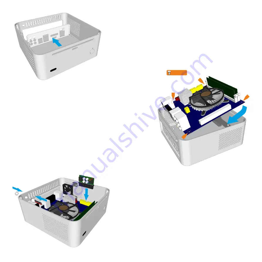
Installing the Motherboard

Locate  the    I/O  shield  that  is  supplied  with  your 
motherboard and firmly push it in place. Ensure that it 
clicks in place fully otherwise the motherboard will be 
difficult to fit.

Carefully lower the motherboard into the chassis, with 
the I/O port  side leading so that the ports can 
fit into the I/O shield.

When the motherboard is correctly in position, fix it to the 
chassis stand-offs using the screws 
provided. Ensure that all the holes correctly align before 
fully tightening the screws.

Connect NanoPSU & Other Cables

With the motherboard in place, you can now connect the 
PSU and any other internal connectors such 
as the power button switch. You should also connect the 
SATA cables in perpetration for installing the 
HDD/ODD cage assembly.

M3 x 4

Содержание FIC evo

Страница 1: ......

Страница 2: ...e and Top Panel Foreword Thank you for your purchase of this Streacom product every care has been taken to ensurethatitmeetswiththehighstandardsthatwehavesetforourselves Should you have any questions that are not covered in this user guide support can be offeredviaemailthroughourwebsiteatwww streacom com Wesincerelyhopethatyouenjoyusingourproduct P2 INDEX ...

Страница 3: ...2 11 Specification Chassis Material Available Colours Motherboard Compatibility HDD Drive Support ODD Drive Support Cooling Method Dimensions Power Supply Support IR Solution Net Weight Aluminum Silver Black sandblast finish Mini ITX 3 x 2 5 depending on components installed Slot loading drive universal eject button 1 x 40x40x10mm or 1 x 60x60x10mm fan not Included 197 197 77mm L W H 3mm feet Nano...

Страница 4: ...ve all 4 screwsandliftthecageoutofthechassis P4 PREPARING FOR ASSEMBLY FittingCoolingFan IRRCModule Optional The F1C Evo can accommodate a 40 or 60mm fan 60mm may interfere with fitting of 2 5 HD see HDD installation The fan cage is packed with the other screws and accessories Fit your purchased fan with 2 screws as shown Depending on 40 or 60mm Fit the fac assembly to the case using a single scre...

Страница 5: ... theI Oport sideleadingsothattheportscan fitintotheI Oshield When the motherboard is correctly in position fix it to the chassisstand offsusingthescrews provided Ensure that all the holes correctly align before fullytighteningthescrews ConnectNanoPSU OtherCables With the motherboard in place you can now connect the PSUandanyotherinternalconnectorssuch as the power button switch You should also con...

Страница 6: ...e vibration if SSD s arenotused Before fitting the slot loading drive affix a self adhesive rubber pad to the drives eject button included in the accessory bag Mount the slot loading drive using 4 screws 2 either side and adjust is position to ensure correct operation of the eject button With left side eject buttons 2 padsmayberequired The primary 2 5 hard drive can be mounted vertically using 2 s...

Страница 7: ...sing 6 screws in total 4 at the top and 2 from underneath Note that the 2 screw underneath fix to the 2 5 hard drive so ensure the correct screwsareused ReplacetheTopPanel With all the components installed all that remains is to replace the top panel and secure it in place with the2longscrewsfromunderneaththechassis When replacing the top panel ensure the correct orientation as the 2 long securing...

Страница 8: ...Melbournestraat 56 3047 BJ Rotterdam The Netherlands www streacom com V1 12 09 ...

Отзывы: