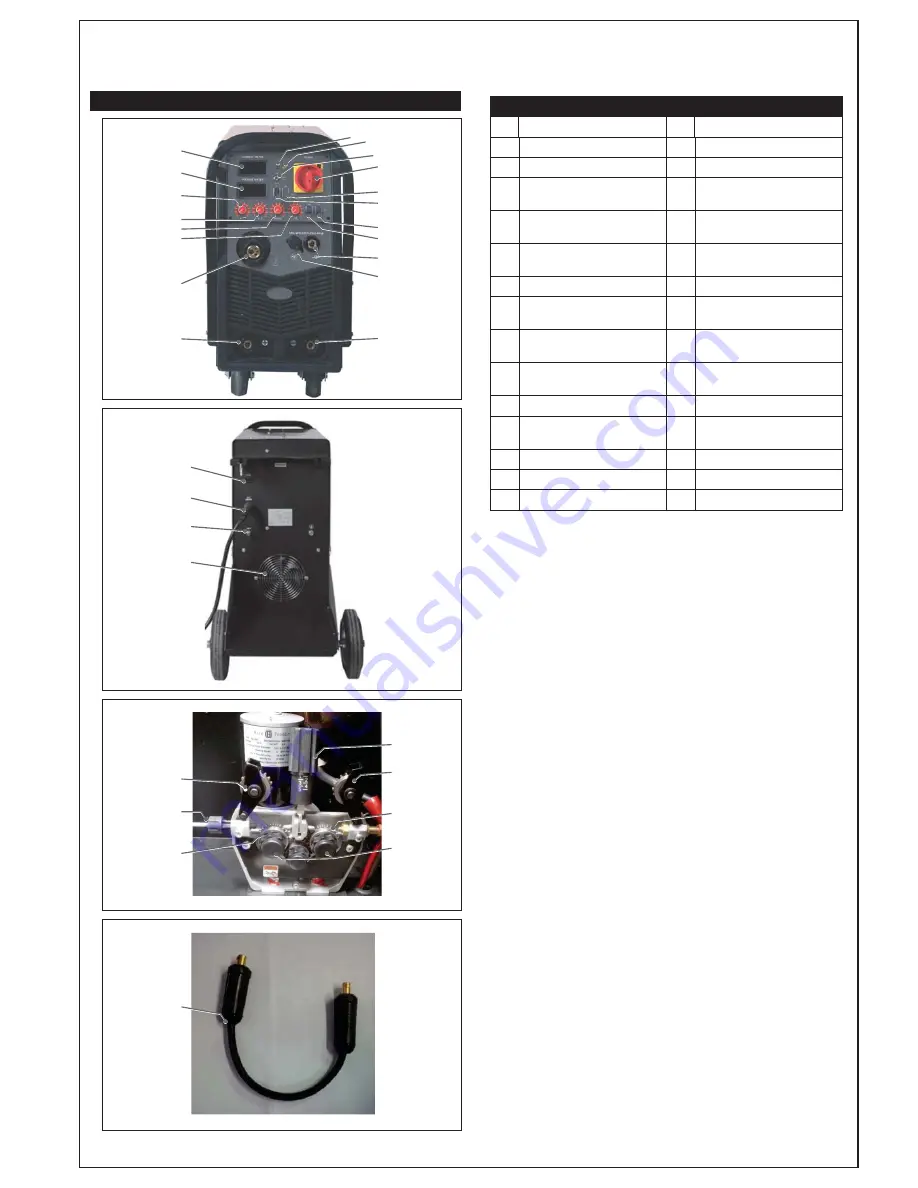
KNOW YOUR WELDER
1
2
16
11
3
10
13
12
15
14
18 19
17
8
9
4
5
6
7
20
21
22
23
25
24
27
26
25
27
28
MIG Power
Connection Lead
Function Reference Table
No.
Description
No.
Description
1
LCD Current Meter
15
Wire Feed Switch
2
LCD Voltage Meter
16
Mains Power Switch
3
MMA/TIG Current
Adjustment Knob
17
Spool Gun Enable Switch
4
MIG Welding Voltage
Adjustment Knob
18
Mains Power Indicator Lamp
5
MIG Wire Feed Speed
Adjustment Knob
19
Overload Indicator Lamp
6
Inductance Adjustment Knob
20
36V AC Auxiliary Power Supply
7
MIG Torch ‘Euro’ Connection
Socket
21
Mains Input Power Lead
8
Positive (+) Welding Power
Output Connection Socket
22
Shielding Gas Inlet
9
Negative (-) Welding Power
Output Connection Socket
23
Cooling Fan
10
Spool Gun Connection Socket
24
Wire Drive Inlet Guide
11
MIG Torch Power Connection
Socket
25
Wire Feed Tension Arm
12
Welding Output Mode Switch
26
Wire Feed Tension Adjustment
13
LIFT TIG Mode Switch
27
Wire Drive Rollers
14
4T/2T Trigger Control Switch
28
Wire Drive Roller Retainer
LCD Display Meters - Current (Ref. 1) and Voltage (Ref. 2)
– These indicate
the actual current and voltage values at the output terminals of the welding
machine. The current meter should read ‘0’ except when welding is actually
taking place. The voltage meter will indicate output voltage during welding
and the welding open circuit voltage when the machine is powered, but not
welding. In MIG mode the open circuit voltage will only appear once the torch
is triggered to activate the circuit. In MMA mode, the open circuit voltage will
show on the display continuously. The digital meters are accurate, and very
sensitive, it is therefore normal to observe some small fluctuations when the
machine is idle.
MIG Control Knobs - Voltage (Ref. 4) and Wire Speed
(Ref. 5)
– The voltage
control adjusts the power in the welding arc, which in turn affects the heat
input and the penetration. The wire speed feed simply controls the rate at
which the welding wire is fed into the weld pool. For any voltage position
setting, there will be a corresponding ‘sweet spot’ in the wire feeding speed
that will give the smoothest and most stable welding arc. The correct wire
feeding speed for a given voltage setting is affected by welding wire type and
size, shielding gas, welding material and joint type. It is recommended to set
the welding voltage as desired and then slowly adjust the wire speed until
the arc is smooth and stable. When reaching this point, if the heat input is too
much / not enough, adjust the voltage setting and repeat the process. If the
operator is unable to achieve a smooth and stable arc with the desired heat
input for the weld, it is likely that a change in wire size and/or shielding gas
type is required.
Inductance Adjustment (Ref. 6)
– Inductance is a property in the welding
output circuit that opposes a change in the flow of current. When MIG welding
with the short circuit arc process, the current stops and starts each time the
wire dips into the weld pool (this happens many times per second). Increased
inductance will slow the rate of current rise/ fall with each dip of the wire and
reduce the rate at which the wire dip transfers take place. This effectively
adjusts the intensity of the welding arc. More inductance will give a softer,
wider arc, typically with less splatter. Less inductance will give a tighter, more
‘sharp’ sounding arc. Optimum inductance settings are affected by many
welding variables such as: material type, shielding gas, joint type, welding
amperage, wire size. Inductance adjustment will have negligible effect with
TIG and MMA welding processes.
Overload Indicator Lamp (Ref. 19)
– Lights when duty cycle is exceeded and
thermal protection is activated. When thermal protection is activated, welding
output will be disabled until the machines cools sufficiently and the overload
indicator lamp goes out.
ZZZVWUDWDFRQ]


