


S/AI
Page 37 of 52
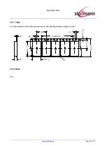
6.4 Placement Recommendation
To achieve best radio performance for S/AI, it is recommended to use the placement
shown in Figure 17. This is a “corner placement” meaning the S/AI is placed such that
the antenna comes close to the corner of the application PCB (red area). So, the yellow area is
outside the PCB and regards to the housing, too (refer to 6.5).
Please note that for best possible performance the antenna should be directed away from the
application PCB as shown in Figure 17.
max.0,5
4,5
10
10
m
ax
.0,
5
10
15
no bare copper (exept solder pads for module)
no copper and components on any layer
no components on any layer
provide solid ground plane(s) as large as possible around
17
do not place any conductive parts in this area
20
20
40
area
Applic. PCB
Figure 17: S/AI Placement Recommendation
6.5 Housing Guidelines
The individual case must be checked to decide whether a specific housing is suitable for the use of
the internal antenna. A plastic housing must at least fulfill the following requirements:
•
Non-conductive material, non-RF-blocking plastics
•
No metallic coating
•
ABS is suggested
6.6 Antenna Issues
S/AI comprises a ceramic antenna which as a component is soldered to the circuit
board. This solution is functional for a S/AI integrated into a plastic housing.
The performance of the antenna has to be checked within the final integration environment.
Adjacent PCBs, components, cables, housings etc. could otherwise influence the radiation pattern
or be influenced by the radio wave energy. It must be ensured that the antenna is not co-located or
operating in conjunction with any other antennas, transmitters, cables or connectors.


