Model 4231G/H
OWNER'S MANUAL
Manual No. 513534 Apr. 2003, Rev. 3
Страница 1: ...Model 4231G H OWNER S MANUAL Manual No 513534 Apr 2003 Rev 3 ...
Страница 2: ......
Страница 3: ...d are certified in the Stoelting Technicare program Model No _______________________ Serial No _______________________ Purchase Date ____________________ Start Up Date ____________________ CALL Distributor _________________________ Phone No _________________________ fill in or affix label ...
Страница 4: ......
Страница 5: ...cetothefreezerwithoutincurringanyobligationtomodifyorprovidenewparts for freezers built prior to date of change DONOTATTEMPTtooperatethefreezeruntilinstructionsandsafetyprecautionsinthismanualare read completely and are thoroughly understood The freezer should be operated only by qualified personnel If problems develop or questions arise in connection with installation operation or servicing of th...
Страница 6: ......
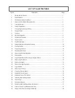
Страница 7: ...0 3 5 Mix Information 11 3 6 Removing Mix from Freezer 11 3 7 Cleaning the Freezer 12 3 8 Disassembly of Freezer Parts 12 3 9 Cleaning the Freezer Parts 14 3 10 Sanitize Freezer and Freezer Parts 14 3 11 Assembly of Freezer 14 3 12 Routine Cleaning 16 4 MAINTENANCE INSTRUCTIONS 17 4 1 Preventative Maintenance 17 4 2 Freeze up 18 4 3 Condenser Service 18 4 4 Extended Storage 18 4 5 Troubleshooting ...
Страница 8: ... 15 Pouring the Mix 10 16 Dispensing Product 10 17 Skimming the Foam 11 18 Removing Mix Inlet Regulator 11 19 Draining Mix 12 20 Auger Flight Wear Front Auger Support Wear 12 21 Removing Front Door 13 22 Removing Spigot 13 23 Removing Auger Supports 13 24 Auger Shafts 13 25 Removing O Ring 13 26 Cleaning Freezer Barrel 14 27 Exploded View of Auger 15 28 Exploded View of Front Door 15 29 Installing...
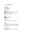
Страница 9: ...mercial soft serve or non dairy mixes available including ice milk ice cream yogurt and frozen dietary desserts This manual is designed to assist qualified service personnel and operators in the insulation operation and maintenance of the Stoelting Model 4231 gravity freezer Information Packet Location Model 4231G RIGHT SIDE SECTION 1 INTRODUCTION Figure 1 Model 4231G Freezer Figure 2 Specificatio...
Страница 10: ... 70 00 178 0 cm high WEIGHT Freezer 640 lbs 291 kg Crated 815 lbs 370 kg ELECTRICAL Refer to the nameplate located on the rear of the Freezer COOLING Air cooledrequires3 7 6cm clearanceforalllouvered panels Water cooled requires pipe or 5 8 inside diameter copper water in be installed for adequate water supply HOPPER CAPACITY Two hoppers 5 6 gallons 21 liters each refrigerated and insulated ...
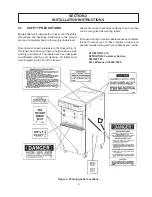
Страница 11: ...bels have been put there to help maintain a safe working environment The labels have been designed to withstand washing and cleaning All labels must remain legible for the life of the freezer Labels should be checked periodically to be sure they can be recognized as warning labels Ifdanger warningorcautionlabelsareneeded indicate the part number type of label location of label and quantity require...
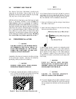
Страница 12: ...ires adequate ventilation Aminimum of 3 7 6 cm of vent space is required for free flow of cooling air at the front and back Fig 4 NOTE For Air Cooled Unit Only A rear block off panel has been provided to prevent recirculation of hot air beneath the freezer The rear block off panel maximizes the efficiency of the freezer See the illustration for the installation instructions 1 Remove both back pane...
Страница 13: ...of electricity B To access the electrical boxes remove the two Phillips head screws on the left and right side panels Then pull the panel down and out NOTE When supply voltage is less than 218V reconnect transformer Switch orange and red wires from transformer at the terminal strip and cap blue wire D Please read decal located on lower electrical box cover Fig 8 The model 4231 freezer is two indiv...
Страница 14: ...6 ...
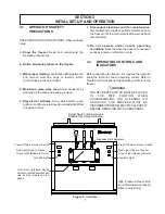
Страница 15: ...der unsafe operating conditions Never operate the freezer if unusual or excessive noise or vibration occurs 3 2 OPERATING CONTROLS AND INDICATORS Before operating the freezer it is requires the operator know the function of each operating control Refer to Figure 9 for the location of the operating controls on the freezer WARNING THE OFF SERVE SWITCH MUST BE PLACED IN THE OFF POSITION WHEN DISASSEM...
Страница 16: ... there is a 3 second delay before the compressor starts Duringthenormaloperation theredPUSHTOFREEZE switchwillilluminateafterthefreezerhasbeeninidlefor the pre set time Before drawing product press the red PUSH TO FREEZE switch if it is illuminated Wait until the green lens is illuminated before dispensing NOTE If the freezer shuts off and the PUSH TO FREEZE light flashes you have an error conditi...
Страница 17: ...itizer in quantities of no less than 2 gallons 7 5 liters of 120 F water Allow sanitizer to contact the surfaces to be sanitized for 5 minutes Any sanitizer mustbeusedonlyinaccordancewiththemanufacturer s instructions CAUTION PROLONGED CONTACT OF SANITIZER WITH FREEZER MAY CAUSE CORROSION OF STAINLESS STEEL PARTS In general sanitizing may be conducted as follows A Push the mix inlet regulator full...
Страница 18: ... mix CAUTION DO NOT OVERFILL THE HOPPER MIX LEVEL MUST NOT BE HIGHER THAN 2 5CM FROM THE TOP OF THE AIR INLET TUBE ON THE MIX INLET REGULATOR E The freezer barrel will automatically fill until it is about full about 3 min If the freezer barrel does not fill check for obstruction in the mix inlet regulator O Ring check for leaks at the mix inlet regulator was installed correctly or that the freezer...
Страница 19: ...ts have a direct bearing on the finished frozen product A change in freezer performance that cannot be explained by a technical problem may be related to the mix When changing from one type of mix to another such a yogurt to Vitari you may have to change the mix inlet regulator and or control settings Please call your distributor for further information Proper product serving temperature varies fr...
Страница 20: ...r the spigots to catch the water When the water has drained turn the CLEAN OFF SERVE switches to the OFF position Allow the freezer barrel to drain completely E Repeat steps A through D using a mild detergent solution 3 8 DISASSEMBLY OF FREEZER PARTS CAUTION PLACE THE CLEAN OFF SERVE ROCKER SWITCHES IN THE OFF POSITION BEFORE DISASSEMBLING FOR CLEANING OR SERVICING Inspection for worn or broken pa...
Страница 21: ...y remove each of the plastic flights with springs Fig 24 F Keep the rear of the auger shafts tipped up once they are clear of the freezer barrels to avoid dropping rear seals G Remove the rear seals H Wipe socket lubricant from the drive end rear of the auger with a cloth or paper towel I Remove all O Rings from parts by first wiping off the lubricant using a clean paper towel Then squeeze the O R...
Страница 22: ...tize the rear of the barrel and drive area by dipping the brush in the sanitizing solution and brushing the rear of the barrel 3 11 ASSEMBLY OF FREEZER To assemble the freezer parts refer to the following steps NOTE Petro Gel sanitary lubricant or equivalent must be used when lubrication of parts is specified NOTE The United States Department of Agriculture and the Food and Drug Administration req...
Страница 23: ... to the surface of the cam on the spigot handle prior to assembly of handle to the spigot body H Install the spigot bodies with O Rings into the front door from the bottom Fig 28 Push straight up until the spigots are in place Install rosette cap I Install the front door on the freezer J Install the circular knobs on the freezer studs Figure 27 Exploded View of Auger Figure 28 Exploded View of Fro...
Страница 24: ...E BEFORE OPERATING FREEZER TO PREVENT DAMAGE FROM POSSIBLE AUGER SEAL LEAKS Figure 30 Drain Trays 3 12 ROUTINE CLEANING To remove spilled or dried mix for the freezer exterior simply wash in the direction of the finish with warm soapy water and wipe dry Do not use highly abrasive materials as they will mar the finish Figure 29 Installing Mix Inlet Regulators ...
Страница 25: ...mmended Use a soft cloth or sponge to apply the cleanser 2 Using a sanitized one pint aluminum overrun container skim the mix in the hopper to remove any foam buildup Fig 31 Figure 31 Skimming Hopper 3 Run a sanitized brush down mix inlet regulator carburetor tubes Fig 32 NOTE When sanitizing the skimmer brush and the hand that holds the mix inlet regulator carburetor must also be sanitized 4 Note...
Страница 26: ...rst place a wet towel over the front of the condenser D Blow out the dirt from the back of the condenser Most of the dirt will cling to the wet towel CAUTION THIS PROCEDURE EMITS A LOUD NOISE E An alternative method is to clean with a condenser brush and vacuum 4 4 EXTENDED STORAGE Refer to the following steps for winterizing the freezer for winter lay up or any extended period of storage A Clean ...
Страница 27: ...irect hot above 100 F Air cooled air away from freezer 3 Condenser is dirty Air cooled 3 Clean See paragraph 4 6 4 Consistency setting too soft 4 Readjust See paragraph 4 2 5 Stabilizers in mix are broken down 5 Remove mix clean sanitize and freeze down with fresh mix 6 Refrigeration problem 6 Check system See note 1 Product is too firm 1 Consistency setting too firm 1 Readjust See paragraph 4 2 2...
Страница 28: ...d or worn spigot O Rings 3 Replace O Rings 4 O Rings or spigot installed wrong 4 Remove spigot and check O Rings 5 Spigot hole in front door nicked or 5 Replace front door scratched Hopper will not 1 EPR valve needs to be adjusted 1 See note 1 Maintain mix 2 Temperature control failure 2 Replace See notes 1 or 2 temperature below 3 Refrigeration problem 3 Check system See note 1 45 F 7 C 1 Must be...
Страница 29: ...ame and quantity needed Common part names and numbers are listed in this manual 5 2 PUSH TO FREEZE LIGHT SWITCH LAMP REPLACEMENT To change a lamp in the PUSH TO FREEZE switch light follow these simple steps A Grasp the lens with your thumb and forefinger and pull out B Remove the faulty lamp by pulling out the lamp puller See Fig 33 Figure 33 Push To Freeze Light Switch Assembly C To install the n...
Страница 30: ...22 ...
Страница 31: ... Weldment 13 2158260 3 Handle 14 570961 3 Pin Cotterless Clevis 15 428045 3 Knob Black Plastic 16 2158082 3 Glide 17 1158080 3 Adjusting Bar 18 647995 3 Screw Machine 20 x 3 50 Long 19 718773 4 Switch 20 647055 8 Screw Machine 4 40 x 625 Long 21 538235 8 Nut Hex 4 40 22 766917 8 Washer Shakeproof 4 23 696048 2 Spring Torsion Outside Spigot 23 696044 1 Spring Torsion Center Spigot 24 694247 3 Sprin...
Страница 32: ...24 ...
Страница 33: ...25 ...
Страница 34: ...26 ...
Страница 35: ...er Joining Bracket W C Only 26 767205 6 Washer Flat 1 4 x 3 4 x 5 16 W C Only Item Stoelting PN Qty Description 29 2172761 2 Water Valve Bracket W C Only 30 644024 4 Screw Mach 8 32 x 1 4 Hx W C Only 31 766941 4 Washer Shakeproof 8 W C Only 32 2172763 2 Pressure Switch Bracket W C Only 33 538335 4 Nut Hex 1 4 20 x 7 16 Stl Zp 34 766456 4 Washer Round 5 8 x 9 32 Steel 35 647393 4 Screw Mach 6 32 x ...
Страница 36: ...28 ...
Страница 37: ...554 2 Module Control Logic Board 608 23 647376 16 Screw Machine 6 32 x 1 4 Lg 24 766933 16 Washer Shakeproof 6 Item Stoelting PN Qty Description 25 718750 2 Switch Rocker 26 732118 16 Terminal Panel Mount Red 27 732119 2 Terminal Housing Red 28 223007 4 Bushing Snap 5 8ID 3 4 Mtg 29 295109 4 Contactor Mag 3 Pole 24V 30 766948 8 Washer Shakeproof 10 Zinc Plate 31 644048 8 Screw Mach 10 24 x 1 2 Hx ...
Страница 38: ...6 1 2A 2B 160 0 0 0 0 0 0 0 0 0 0 0 0 0 0 0 0 0 0 0 0 0 0 0 0 0 0 0 0 0 1 1 1 1 1 3 3 3 3 3 0 0 0 0 0 0 0 0 0 0 2 2 2 2 2 12 13 14 12 13 14 12 13 14 3 15 9 9 6 1 2A 2B 15 3 16 7 7 7 7 7 7 7 7 7 7 7 7 7 7 7 7 5 5 5 5 5 0 0 0 0 0 2 2 2 2 2 ...
Страница 39: ...2 Condenser W C Only 4A 284044 1 Condenser A C Only 5 718686 2 Switch Pressure W C Only 6 342008 2 Drier Filter 7 762277 2 Check Valve Magni Chek 8 762445 2 Expansion Valve 9 342020 2 Drier Refrigeration 10 458010 2 Indicator Sight Glass 11 763455 2 Valve Solenoid 12 375813 6 Access Fitting Assembly 13 282085 6 Cap Quick Seal 14 762359 6 Valve Core 15 231101 SV 2 Capillary Tube 16 1158278 2 Valve ...
Страница 40: ...0 0 0 0 0 0 0 0 0 0 0 0 0 0 0 0 0 0 0 0 0 0 0 0 0 0 1 1 1 1 1 3 3 3 3 3 0 0 0 0 0 0 0 0 0 0 2 2 2 2 2 12 13 14 12 13 14 12 13 14 3 15 9 9 6 1 2A 2B 15 3 16 7 7 7 7 7 7 7 7 7 7 7 7 7 7 7 7 5 5 5 5 5 2 2 2 2 2 1 1 1 1 1 172 2 2 2 2 17 5 2 2 2 2 2 5 6 6 6 6 6 ...
Страница 41: ...2 Condenser W C Only 4A 284044 1 Condenser A C Only 5 718686 2 Switch Pressure W C Only 6 342008 2 Drier Filter 7 762277 2 Check Valve Magni Chek 8 762445 2 Expansion Valve 9 342020 2 Drier Refrigeration 10 458010 2 Indicator Sight Glass 11 763455 2 Valve Solenoid 12 375813 6 Access Fitting Assembly 13 282085 6 Cap Quick Seal 14 762359 6 Valve Core 15 231101 SV 2 Capillary Tube 16 1158278 2 Valve ...
Страница 42: ......
Страница 43: ...ies are subject to the conditions that Buyer a signs and returns to Stoelting upon installation the Checklist Warranty Registration Card for the affected equipment b gives Stoelting prompt written notice of any claimed breach of warranty within the applicable warranty period and c delivers the affected equipment to Stoelting or its designated service location in its original packaging crating also...