6
www.stockmastereurope.nl
Mounting Bracket Assembly
IMPORTANT
:
To avoid assembly problems follow these instructions exactly.
Step 1
-
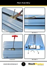
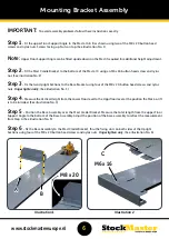
Fit the upper Floor Support Angle to the Mast at A & B as shown using two of the M8 x 20 button head
screws and nyloc nuts. Screws facing up. Nuts on top. (See illustration No. 1)
Note:
Upper Floor Support Angle can be fitted upside down on the Mast if required for additional height adjustment.
Step 2
-
Fit the Mast Cradle Bracket to the bottom of the Mast at C using an M6 x 16 button head screw and nyloc
nut. (See illustration No. 2)
Step 3
-
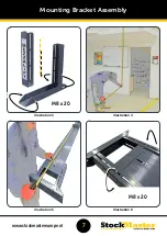
Fix the two Upright Sections to the Base Bracket using four of the M8 x 20 button head screws and nyloc
nuts.
Finger tighten only
.
(See illustration No. 3)
Step 4
-
Measure the Vertical Height from the Lower Floor level to the Uppr floor level at the position the Mezz-a-lift
is to be intsalled. (See illustration No. 4)
Step 5
-
Position the Base Assembly over the Mast Cradel Bracket. Measure the total length from the upper Floor
Support Angle to the bottom of the Base Assembly. Adjust the position of the base assembly to reflect the measurement
from Step 4. (See illustration No. 5)
Step 6
-
Fix the Base Assembly to the Mast Cradel Bracket, thru the fixing slots on both sides of the Upright
Sections using four of the M8 x 20 button head screws and nyloc nuts.
Finger tighten only.
(See illustration No. 6)
Illustration 1
Illustration 2
B
A
M8 x 20
M6 x 16
C

