IMPORTANT
:
To avoid assembly problems follow these instructions exactly.
Step 1
-
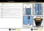
Remove the M6 x 65mm screw and nyloc nut at A from the LHS Upper Side Safety Rail as viewed from the
entry point of the platform and discard. (See illustration No. 1)
Step 2
-
Align the Rear Tab of the Auto-Safe Gate Housing with hole position A in the LH Side Upper Safety Railing.
Insert the longer M6 x 70mm screw supplied and tighten with a nyloc nut. (See illustration No. 2)
Step 3
-
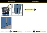
Fit the supplied U Bolt around the Upper Side Safety Rail and pass thru the holes in the Auto Safe Gate
Housing. Ensure the Gate is level and tighten using the washers and nyloc nuts supplied. (See illustration No. 3)
Step 4
-
Open and close the gate testing the Spring Auto Open Function and that the Gate Latch securely holds
the gate in the closed position. (See illustration No. 4)
Auto-Safe Gate Assembly
Illustration 1
Illustration 2
Illustration 3
Illustration 4
A
M6 x 70
A
M6 x “U” Bolt
M6 x “U” Bolt
7
8
NEXT:
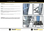
Proceed to Ladder Frames Assembly.
9


