background image

IMPORTANT

To avoid assembly problems follow these instructions exactly.

Step 1 

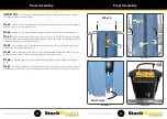
On a level surface lay the mast face-down as shown. (See illustration No. 1)

Step 2 

Remove the Nut from the Winch Shaft at A. Pull out the winch shaft and remove the Sproket. Carefully put 

the Sproket, Shaft, Nut & Washer aside. Parts to be re-assembled in Step 4. (See illustration No. 2) 

Step 3

 - 

Place the Winch Body inside the opening on the back of the Mast. Insert the Winch Body at 45 degrees so 

the Chain fits inside the Winch Body.(See illustration No. 3)

Step 4

 - 

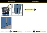
Fix the Winch Mounting Bracket to the Mast at B & C using two of the M6 x 16 button head screws and nyloc 

nuts. 

Finger tight only. 

(See illustration No. 4) 

Step 5

 -

  Adjust the Winch Mounting Bracket so you can slide the Sproket back into place. Insert the Winch Shaft at 

D and re fit the washer and nut. Fix the Winch Mounting Bracket to the Mast at E using an M6 x 16 button head screw and 
nyloc nut. Tighten the Winch Shaft and nut firmly then tighten the Winch Mounting Bracket screws and nuts at B, C, & E 
(See illustration No. 5)

Winch Assembly

Illustration 1

Winch Assembly

Illustration 2

Illustration 3

Illustration 4

Illustration 5

A

B

C

M6 x 16

E

D

M6 x 16

27

28

 NEXT:

 Proceed to Chain Setting.

29

Содержание Lift-Truk

Страница 1: ...Pro Version shown Assembly Instructions CL INST04...

Страница 2: ...rm Kickrail Slide the Safety Rail into the Kickrail Place a M6 x 40mm bolt through the top hole at the front of the Kickrail and fit a nut Finger tight only See illustration No 2 Step 3 Fix the Lower...

Страница 3: ...m Safety Rail Assembly Illustration 5 Illustration 6 M6 x 70 Platform Safety Rail Assembly 3 4 NEXT For PRO Models Proceed to Rota Gate Assembly 5 NEXT For Standard Models Proceed to Ladder Frame Asse...

Страница 4: ...se the Rotating Side Safety Rail as shown Twist the Locking Knob 1 4 turn so the pin is fully extended and locate the pin in the Stricker Plate at E Tighten all bolts at A thru D untill firm only See...

Страница 5: ...ew supplied and tighten with a nyloc nut See illustration No 2 Step 3 Fit the supplied U Bolt around the Upper Side Safety Rail and pass thru the holes in the Auto Safe Gate Housing Ensure the Gate is...

Страница 6: ...e together using a 10 x 20mm bolt and nut Finger tight only For ease lift the Frame up slightly Remove the Tube Brace from under the Platform Safety Rail and fit to the other side See illustration No...

Страница 7: ...Ladder Frame Assembly Illustration 5 Illustration 6 M10 x 20 M10 x 20 Ladder Frame Assembly 11 12 NEXT Proceed to Tube Brace Assembly 13...

Страница 8: ...11 ONLY fix the other end of the Tube Brace at B on the Rear Frame then turn the ladder over and repeat for the other side Note Do not tighten the M10 bolts until advised For sizes 8 to 11 ONLY Procee...

Страница 9: ...pass it through the loop in the Restraining Cable and fit the second washer Fit the bolt in the Upper hole of the Mounting Angle of the Step Frame and secure with a nut Tighten the bolt using the Doub...

Страница 10: ...e at the front of the Kickrail and fit a nut Finger tight only See illustration No 1 Step 2 Fix the Handrail to the Step Place an M6 x 40 bolt through the Handrail and fit the nut under the Step Check...

Страница 11: ...sitioned in the direction of the arrow Hold the Castor in the position illustrated as you tighten See illustration No 5 Step 6 Attach the Mobilisation Link Cable to the Control Handle Fit a Clevis Pin...

Страница 12: ...stration 5 Illustration 6 C Mobilisation Assembly Illustration 7 Illustration 8 E F 21 22 NEXT For sizes with 4 to 7 steps incl platform Proceed to Winch Assembly Instructions 27 NEXT For sizes with 8...

Страница 13: ...using four of the M6 x 16 button head screws Ensure Mast sections are correctly aligned and then tighten all screws See illustration No 3 Step 4 Lift the Mast as shown cut and remove the Wire Tie then...

Страница 14: ...Illustration 5 Illustration 6 Illustration 7 Illustration 8 A B 2 Piece Mast Assembly 2 Piece Mast Assembly 25 26 NEXT Proceed to Winch Assembly 27...

Страница 15: ...ustration No 3 Step 4 Fix the Winch Mounting Bracket to the Mast at B C using two of the M6 x 16 button head screws and nyloc nuts Finger tight only See illustration No 4 Step 5 Adjust the Winch Mount...

Страница 16: ...the Chain around the Sprocket using the Large White Wire Tie Once the Chain is engaged correctly cut and remove the Wire Tie See illustration No 2 Step 3 Slide the Chain Roller toward the bottom of t...

Страница 17: ...e hole at the Mast centre See illustration No 3 Step 4 Place the Winch Cover over the Winch Fix the top of the cover to the C slots of the Mast using the Self Tapping Screws at E and F See illustratio...

Страница 18: ...Mast Assembly Illustration 5 Illustration 6 Illustration 7 G G Mast Assembly 33 34 NEXT Proceed to Lift Table Assembly 35...

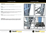
Страница 19: ...sing the M10 x 20mm bolts and nyloc nuts Fix the Lower Table Brackets to the Mast Carraige at the hole position relative to your model Leave bolts slightly loose See illustration No 3 Step 4 Fix the L...

Страница 20: ...MENT This completes the product assembly Before use See the product Risk Assesment at www stockmaster co WARRANTY Thank you for choosing Stockmaster your safety is in good hands Register your 2 year w...

Отзывы: