


JC-4s manual version 9.1 page 3
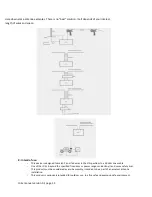
Pin 2: (Grey) is the Start commando to the tuner to start the tuning process.
If you connect this wire momentarily (pulse) to the GROUND the tuner will start tuning if RF power is
sended via the Coax Cable.
Pin 3: (Yellow/Green) This is the key (not ptt) connection. When the tuner is “tuning” it will send back a
voltage to a LED. (in the control box). When the tuning process is finished the led will go off.
Pin 4: (black) This is the control cable to switch antenna out A of B of the tuner.
If you connect pin 4 to the ground the tuner will use output A. If you connect pin 4 to +12V DC the tuner
will use output B. If you connect nothing to pin 4, The tuner output A and B will be connected internally
to the ground inside the tuner.
So the owner of the tuner can easy make his own design control box to his own demands.
Just open the small control box and discover how simple the design is.
The longer wires color RED and BLACK must be connected to your power supply. Logical, RED is the
positive connection.
Remember that if you do NOT use the same power supply for your transceiver and antenna tuner you
must add a jumper wire from the ground of the transceiver to the “-“ of your external power supply.
(So the Black of the red/black cable MUST be connected to the ground (chassis) of the radio)
This jumper wire is not provided with the tuner and can be any wire. (See diagram examples)
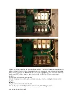
Pin 4 has to be explained more in combination with the jumper-switch inside the tuner on the top
board.
Very nearby the output A and B connectors you will find this jumper. Default this switch is jumpered to
the GROUNDED position. (totally left position) (see picture on next page)
Содержание JC-4s
Страница 12: ...JC 4s manual version 9 1 page 12 ...