UM0922
Block diagram
Doc ID 17259 Rev 1
7/23
4 Block
diagram
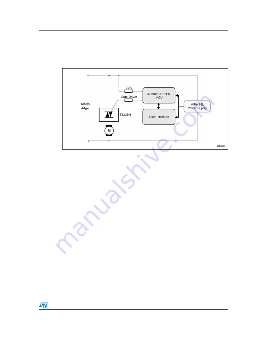
The universal motor control system can be divided into a few simple blocks.
Figure 2.
STEVAL-IHM029V1 block diagram
Power supply
The power supply is designed using a buck converter topology and is based on the
VIPer16LN, which works at a fixed frequency of 60 kHz. The wide range input voltage (90-
265 VAC, 50/60 Hz), allows the demonstration board to operate at either 110 VAC/60 Hz, or
220 VAC/50 Hz. The converter output voltage is -12 VDC. This voltage is sent to a L7905CP
linear regulator, which in turn provides a reference voltage of -5 VDC. The negative power
supply is highly recommended when driving a Triac directly with a microcontroller.
ZVS
The zero-voltage switching signal is captured directly from the input mains. The MCU
detects the ZVS after each period of the input mains, and synchronizes the routines and
events accordingly (i.e. the driving of the Triac).
User interface
The user interface consists of a potentiometer to adjust the output power level, and 6 LEDs
to indicate the status and the power level of the board.
Motor driving
The universal motor is driven by a high temperature Triac in phase-angle control.
STM8S103F2
The entire process is controlled by a 20-pin, 8-bit STM8S103F2 microcontroller.


