


EN - 7
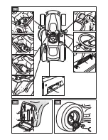
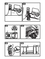
4.2 STEERING WHEEL ASSEMBLY
1.
Put the machine on a flat surface
and straighten the front wheels.
2.
Link the connector (Fig. 3.A) to the hour
meter (Fig. 3.B) fixed in the rear part
of the dashboard cover (Fig. 3.C).
3.
Mount the hub (
fig. 4.A)
on the shaft
(
fig. 4.B)
, making sure that the plug (
fig. 4.C)
is correctly fitted into the hub seat.
4.
Fit the dashboard cover (
fig. 4.D)
clicking
the seven fasteners into place.
5.
Fit the steering wheel (
fig. 4.E)
onto
the hub (
fig. 4.A)
with the spokes
directed towards the seat.
6.
Fit the spacer (
fig. 4.F
) and fasten the
steering wheel in place using the screws
supplied (
fig. 4.G)
in the indicated order.
7.
Fit the steering wheel cover (
fig. 4.H)
by clicking the fasteners into place.
4.3 SEAT ASSEMBLY
Fit the seat (fig. 5.A) onto the plate (fig. 5.B) using
the screws (fig. 5.C).
4.4 MOUNTING AND CONNECTING
THE BATTERY
The battery (fig. 6.A) is housed under the seat
and secured by a spring (fig. 6.B).
1.
First connect the red wire (
fig. 6.C)
to
the positive pole (+) and then the black
wire (
fig. 6.D)
to the negative pole (–),
using the screws supplied as shown.
2.
Apply silicone grease to the terminals
and check that the protective cap for
the red wire (fig. 6.E) is in place.
IMPORTANT
Always fully charge the battery
according to the instructions in the battery book
-
let.
IMPORTANT
To prevent the safety device in
the electronic circuit board from cutting in, never
start the engine until the battery is fully charged!
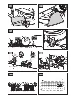
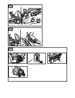
4.5 MOUNTING THE REAR BUMPER
1.
1a.
For type "l" bumpers only -
Mount the front
bumper (fig. 7.A) on the bottom of the frame
(fig. 7.B) using the four screws (fig. 7.C).
1b.
For type “II” bumpers only
1.
Fit the two brackets
(fig. 8.A)
and
(fig.
8.B) to the bottom of the frame
(fig. 8.C)
following the direction of assembly
indicated in the figure: R= right; L= left.
2.
fully tighten the screws (
fig. 8.D)
.
3.
Attach the front bumper (fig. 8.E) to the
brackets (fig. 8.A) and
(
fig. 8.B) using
the screws (
fig. 8.F) and nuts
(
fig. 8.G).
4.6
MOUNTING THE CUTTING-
MEANS ASSEMBLY SIDE
REINFORCEMENTS
(IF FORESEEN).
Complete the mounting of the cutting-means
assembly by fitting the side reinforcements
on the cutting-means assembly profile
using the screws supplied (fig. 9)
4.7 MOUNTING THE SIDE GUARDS
OF THE CUTTING DEVICE
ASSEMBLY (IF ANY)
Mount the safety panels (fig. 10.A)
using the screws (fig. 10.B) and
nuts (fig. 10.C) supplied..
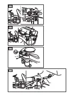
4.8 SIDE DISCHARGE CHUTE ASSEMBLY
1.
From the inside of the side discharge chute
(fig. 11.A), fit the spring (fig. 11.B) by
inserting the terminal (fig. 11.B.1) into the
hole and turning it so that both the spring
(fig. 11.B) and the terminal (fig. 11.B.2)
are securely positioned in their seatings.
2.
Position the side discharge chute (fig.
11.A) in line with the cutting-means
assembly brackets (fig. 11.C). Using a
screwdriver, turn the second terminal (fig.
11.B.2) of the spring (fig. 11.B) to bring
it outside the side discharge chute.
3.
Fit the pin
(fig. 11.D)
in the holes on the
brackets
(fig. 11.C)
and on the side discharge
chute, so that it passes through the coils
of the spring
(fig. 11.B)
and the drilled end
comes out of the inner most bracket.
4.
Insert the cotter pin
(fig. 11.E)
in the pin
(fig. 11.D)
hole
(fig. 11.D.1)
and rotate the
pin until it is possible to bend the two ends
(fig. 11.E.1)
of the cotter pin, (with the aid
of a pair of pliers), so it cannot slide out
and cause the pin to fall out
(fig. 11.D)
.
Check that the spring works
correctly and keep the side discharge
chute securely lowered. Make sure that
the pin is fitted properly to prevent
it from falling out accidentally.
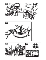
IMPORTANT
For models with optional side
unloading: make sure that the side unloading
guard (Fig. 15.A) is lowered and locked by the
safety lever (Fig. 15.B).
Содержание SDNSL 108 Hydro
Страница 2: ......
Страница 3: ...ITALIANO Istruzioni Originali IT ENGLISH Translation of the original instruction EN ...
Страница 5: ...5 3 A B C D E A F G H A A B C 4 B C C A 6 A B C D E ...
Страница 6: ...7 I II A C C B OK NO A B C D D E F F G G 8 9 ...
Страница 7: ...10 A B B C C 11 B 2 A C B 2 A D C B D 1 E D E 1 A B B 1 B B ...
Страница 8: ...12 J A B C D E E 1 F G H I L E F II I 13 14 A A ...
Страница 9: ...15 A B 16 B A 17 A H H 30 mm H 10 mm H 20 mm H 0 mm A C B D 18 max 10 17 19 A 20 1 3 21 A B ...
Страница 10: ...22 A 23 24 25 B C A ...
Страница 11: ...27 A B C A B C A 26 I II A A 28 29 A A B C ...
Страница 12: ...A 110 mm 30 31 32 33 B A C C 34 A D B C 35 A B A A B C ...
Страница 13: ...36 A A 37 38 B C D A2 ...
Страница 38: ...STIGA S p A Via del Lavoro 6 31033 Castelfranco Veneto TV ITALY Type s n Art N stiga com ...


