EN - 9
4.3 IDENTIFICATION LABEL
The identification label includes
the following data (fig. 1):
1.
Sound power level.
2.
CE conformity marking.
3.
Year of manufacture.
4.
Type of machine.
5.
Serial number.
6.
Name and address of Manufacturer.
7.
Article code.
8.
Max. motor operation speed.
9.
Weight in kg.
10.
Electrical protection rating.
11.
Rated voltage.
12.
Battery capacity.
Write the identification data of the
machine in the specific space on the
label on the back of the cover page.
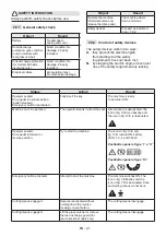
SAFETY INSTRUCTION
State the identification data on the product
identification label whenever you contact
an Authorised Service Centre.
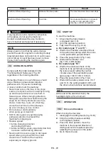
NOTE
An example of the Declaration of Conformity
is provided on the last pages of this manual.
4.4 MAIN COMPONENTS
The machine comprises the following
main components having the
following functions (Fig.1 ):
A. Cutting means assembly:
this is
the assembly comprising the casing
housing the rotating cutting means
assembly and the cutting means.
B. Cutting means
: these are what cut the
grass; the fins at the ends help convey the
cut grass towards the discharge chute.
C. Side discharge chute:
it is a safety
protection and prevents any objects
collected by the cutting means from
being thrown away from the machine
(only for models with side discharge).
D. Discharge chute:
this is the part
connecting the cutting means
assembly to the grass catcher
(for
models with rear collector only).
E. Grass catcher:
in addition to collecting
the mown grass, the grass catcher also
constitutes a safety element, since it
prevents any objects picked up by the
cutting means from being projected
long distance from the machine
(for
models with rear collector only).
F. Rear discharge guard (available upon
request):
this can be fitted in place of
the grass catcher and prevents objects
from being drawn up by the cutting
means and hurled away from the machine
(for rear collection models only).
G. Driving seat:
this is where the
machine operator sits. It has a sensor
connected to safety devices for detecting
the presence of the operator.
H. Blade motor
: drives the cutting means.
I. Drive motor
: drives the wheels.
J. Battery
: provides power to the motor and
all electrical components of the machine.
K. Front bumper:
this protects the
front section of the machine.
L. Steering wheel:
turns the front wheels.
M. Pushbutton panel
: interface
comprising all the main commands
for using the machine.
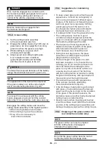
5. ASSEMBLY
WARNING
The safety regulations to follow are described in
chap. 2. Strictly comply with these instructions
to avoid serious risks or hazards. Do not use the
machine until all the instructions provided in the
“ASSEMBLY” section have been carried out.
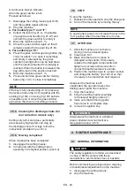
For storage and transport purposes,
some components of the machine are
not installed in the factory and have to
be assembled after unpacking.
Unpacking and completing the assembly should
be done on a flat and stable surface, with enough
space for moving the machine and its packaging,
always making use of suitable equipment.
Содержание MPST 84 Li 48 V1
Страница 2: ......
Страница 5: ...F A E G H C B A D E F G A H C B A D B C C A 4 3 I II ...
Страница 6: ...A C C B OK NO A B C D D E F F G G B 2 A C B 2 A D C B D 1 E D E 1 A B B 1 B B 5 I II 6 ...
Страница 7: ...A B B A 8 7 9 ...
Страница 8: ...A B C C D D H H E G F G F E 5 H H I I I I J K O N L O N M 10 15 cm A A C B III 10 11 ...
Страница 10: ...1 3 A B A A A C B 14 15 16 17 18 19 20 ...
Страница 11: ...I II A A B A 1 B A D C B A E TEST BEFO RE USE TEST RESET 22 23 21 25 24 ...
Страница 12: ...A 28 A 26 A H H 30 mm H 10 mm H 20 mm H 0 mm 27 A C B D A C B A H 29 30 ...
Страница 13: ...31 A A B C 180 mm 110 mm 32 33 ...
Страница 14: ...38 B A C C 39 A D B C A A B C 110 mm 34 35 A A 36 37 ...
Страница 15: ...42 A B C D D 41 43 40 A B I II ...
Страница 16: ...A1 A2 B D C H J F I E m a x 2 4 5 N 2 5 k g m a x 9 8 0 N 1 0 0 k g C G K 44 ...
Страница 223: ......
Страница 224: ...ST S p A Via del Lavoro 6 31033 Castelfranco Veneto TV ITALY dB LWA Type s n Art N ...


