


4
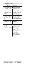
46.
Danger of cutting yourself Cutting means Do not put
hands or feet near or under the opening of the cut-
ting means
47.
Beware of hot surfaces
OPERATING INSTRUCTIONS
For information on the engine and the battery if sup
-
plied read the relevant owner manuals
NOTE – The number which precedes each paragraph
links the references in the text to the respective illus
-
trations listed on page iii and following pages
1. COMPLETE ASSEMBLY
NOTE
The machine can be supplied with some parts al-
ready assembled
WARNING!
Unpacking and completing the assem-
bly should be done on a flat and stable surface, with
enough space for moving the machine and its packag-
ing, always making use of suitable equipment.
Disposal of the packaging should be done in accord-
ance with the local regulations in force.
1.1 Assembling the handle
• Model 474:
i
Assemble one of the ends of the lower part of the han
-
dle using one of the two lower knobs and relative
screws
previously removed from their respec
-
tive holes.
ii
Screw on the knob to about half way along the
screw thread
iii
Assemble the other end of the lower part of the han
-
dle and lock into position using the second lower
knob and relative screws
iv
Fully tighten the two knobs
• Model 504:
Assemble the lower part of the handle and secure
in place using the lower knobs
previously removed
from their respective holes
Assemble the top part using the knobs and sup
-
plied screws
Fit the cable fasteners as shown and secure the con
-
trol cables.
• Manual ignition models
Electric key ignition models
Fit the starter cable in the guide spiral (6) and tighten
the nut (7).
1.2
Battery connection
Electric key ignition models
Connect the battery cable to the general wiring connec
-
tor on the lawnmower
• Electric push-button ignition models
Follow all the instructions provided in the engine
Instruction Manual.
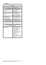
2. CONTROLS DESCRIPTION
NOTE
The meanings of the symbols on controls are ex
-
plained in the previous pages.
2.1
Throttle lever
The throttle is controlled by the lever
Lever positions are indicated on the relevant plate.
Some models have a xed speed engine with no need for
a throttle.
2.2
Engine brake lever cutting means
The cutting means brake is controlled by the lever which
must be held against the handle during ignition and during
lawnmower operations
The engine stops when the lever is released
2.3
Drive lever where applicable
On power driven models push the lever toward the han
-
dle for forward movement
The lawnmower stops moving forward when the lever is
released.
The engine must always be ignited with the drive disen
-
gaged.
WARNING!
To prevent damage to the transmis-
sion, do not pull the machine backwards with the trans-
mission engaged.
2.4
Converter control lever if tted
In the models with drive systems the converter control le
-
ver if tted allows the operator to regulate forward gear
speed.
To do so move the lever following the indications pro
-
vided near the control lever.
IMPORTANT
The engine must be running and the drive
engaged when switching from one speed to another.
Do not touch the converter control when the engine is
stopped. Doing this could damage the converter.
NOTE
If the machine does not move forward with the le-
ver in the «
position simply move the lever to
» and
then immediately return to the
» position.
2.5 Cutting height adjustment
The cutting height is adjusted by the levers
The four wheels must be adjusted to the same height
DO THIS WHEN THE CUTTING MEANS IS STATIONARY.
3. GRASS CUTTING
3.1a
Preparation for mowing and mulching
On models with side discharge make sure that the side
discharge guard is lowered
3.1b
Preparation for mowing and side discharge
of grass if provided
Lift the side discharge guard and t the side discharge
chute as illustrated in the diagram
– Close the side discharge guard (1) so that the side dis-
charge chute is locked in place
3.2 Engine ignition
During ignition follow the instructions in the engine manual
• Manual ignition models
Pull the cutting means brake lever against the handle
and rmly tug the knob on the ignition cable
Electric key ignition models
Pull the cutting means brake lever against the handle
Содержание MCS 474 Series
Страница 4: ...ii 41 42 43 46 47 21 22 23 24 25 26 27 27 ...
Страница 5: ...iii MCS 474 Series 1 1 2 1 1 2 ...
Страница 6: ...iv 2 5 I III II IV 3 1a 3 1b MCS 474 Series MCS 504 Series 2 3 2 2 2 4 ...
Страница 7: ...v 3 3 3 2 3 4 4 2 MCS 474 Series MCS 504 Series ...
Страница 12: ......
Страница 19: ...1 A B BG C ...
Страница 20: ...2 D ...
Страница 21: ...3 E G mulching mulching ...
Страница 23: ...5 2 1 2 2 2 3 2 4 2 5 3 1a mulching 3 1b 3 2 3 3 MULCHING MULCHING ...
Страница 24: ...6 3 4 O 3 6 AVS 7 4 1 ii 4 2 4 3 4 4 ...
Страница 25: ...7 p ...
Страница 26: ......
Страница 52: ......
Страница 53: ...1 A B EL A C ...
Страница 54: ...2 D ...
Страница 55: ...3 E G mulching ...
Страница 57: ...5 2 2 T 2 3 2 4 2 5 3 1a mulching 3 1b 3 2 3 3 MULCHING 3 4 ...
Страница 58: ...6 3 6 AVS 4 1 vi 4 2 4 3 4 4 ...
Страница 59: ...7 ...
Страница 60: ......
Страница 115: ...1 A B e MK C ...
Страница 116: ...2 D ...
Страница 117: ...3 E G ii 1 2 CE 3 4 5 6 7 8 9 ...
Страница 118: ...4 11 12 13 14a 14b 15 16 17 18 21 22 23 24 25 26 27 41 42 43 46 47 1 1 i ii iii iv 1 2 2 1 2 2 2 3 ...
Страница 119: ...5 2 4 2 5 mulching 3 1b 3 2 3 3 MULCHING MULCHING 3 4 ...
Страница 120: ...6 3 AVS 4 1 vi 4 2 4 3 4 4 ...
Страница 121: ...7 ...
Страница 122: ......
Страница 142: ......
Страница 155: ...1 A B RU C ...
Страница 156: ...2 D ...
Страница 157: ...3 E G ...
Страница 158: ...4 ii 1 2 CE 3 4 5 6 7 8 9 11 12 13 14a 14b 15 16 17 18 21 22 23 24 25 26 27 41 B 42 43 46 47 iii 1 1 i ii iii iv ...
Страница 159: ...5 1 2 2 1 2 2 2 3 2 4 2 5 K 3 1a 3 1b 3 2 3 3 ...
Страница 160: ...6 3 4 3 6 AVS 4 1 vi 4 2 4 3 ...
Страница 161: ...7 4 4 ...
Страница 162: ......


