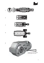
During assembly, it must be ensured in addition
that the rotary shaft seals do not become soiled,
damaged or coated with paint. When lacquering
the units, cover or protect with grease all sealing
rings and running surfaces of the shafts. This is
the only way to prevent damage and thus the
loss of oil.
Then secure the gears using a hexagon head
cap screw and a disk (see fig. 2 page 21).
Assembly of Shrinking Disk
The shrinking disks are ready to install and well
greased internally when supplied. Remove the
separators which are fitted between the outer
rings of the shrinking disks for transport before
tightening the clamp bolts. When fitting the
shrinking disks onto the secondary part to be
braced, the seating point of the secondary part
for the shrinking disk must be greased. In the
area of the shrinking disk seat, the bore hole of
the hub and the shaft must be free of grease.
Never tighten the screws on the shrinking
disks
before
the
connection
has
been
completely assembled: the shrinking disk
and hub can become permanently deformed,
rendering them unusable.
Tightening the Shrinking Disk
Tighten clamp bolts evenly and in order using a
wrench of appropriate length in several stages,
ensuring that the disks remain plane-parallel to
each other. A tightening angle of approximately
30° is usually a suitable average value. Finally
check the prescribed starting torque of all
screws and bolts with a torque wrench.
Tightening torques:
Screws grade 10.9
M5: 4 Nm; M6: 12 Nm; M8: 30 Nm; M10: 59 Nm
M12: 100 Nm; M16: 250 Nm; M20: 490 Nm
Screws grade 12.9
M6: 13 Nm; M8: 32 Nm; M10: 65 Nm M12: 120 Nm;
M16: 290 Nm; M20: 570 Nm
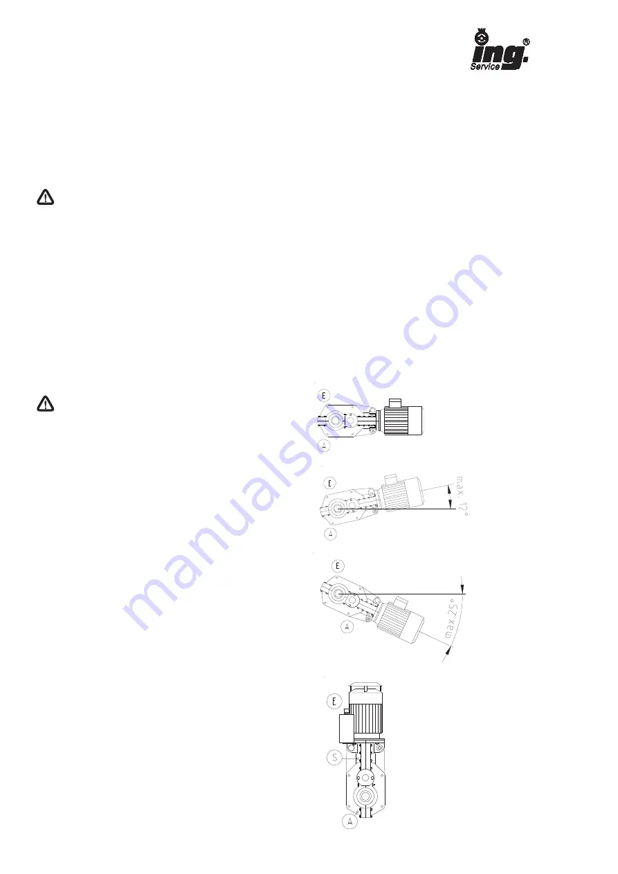
Installation positions
The QuarryMaster
®
series helical bevel gears
can be operated without changing the oil
quantity (see nameplate) in the installation
positions
1-4.
The
maximum
admissible
inclination is to be considered!
Do not install gearboxes in brake motor
execution with motor downward since with
wear of seals withdrawing oil can affect the
function of the brake.
With installation position V1 (index number 5-8)
fill in lubricant to the oil level bore. The
ventilation has to be screwed into the oil
expansion tank at the position named E.
11
E
®
position ventilation
A
®
position oil drain
S
®
position oil level
direction V1


