background image

8

 | WPL  33  HT 

WWW.sTiebeL-eLTron.com

insTaLLaTion  


PreParaTions

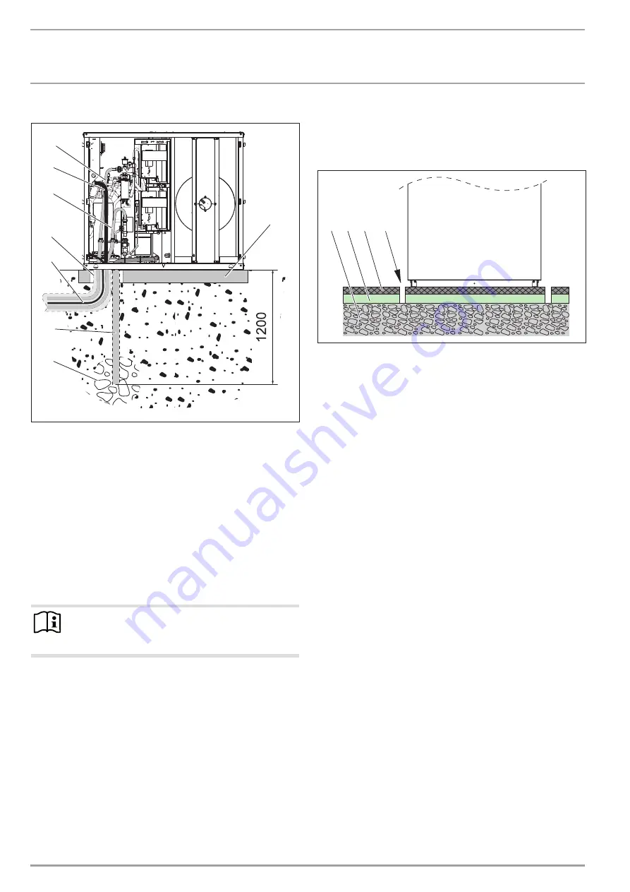
example: installation on foundations

26

�0

3�

01

�1

55

4

1

3

4

5

7

6

8

2

1  Heating circuit flow

2  Main power cable

3  Heating circuit return

4  Conduit for supply lines

5  Electric cables

6  Drainage pipe

7  Gravel bed

8  Foundation

f

f

Only use weather-resistant cables.

f

f

Protect the flow and return pipes against frost with sufficient 

thermal insulation. Provide thermal insulation in accordance 

with applicable regulations.

f

f

Also protect all supply lines/cables against humidity, damage 

and UV radiation by means of a conduit.


Note

When routing the condensate hose, observe chapter “In-

stallation / condensate drain”.

9.2.3  preparation of the installation site for internal 

installation

f

f

Observe chapter “Sound emissions for internal installation”.

f

f

Isolate the installation surface.

1 2 3

4

26

�0

3�

01

�1

46

6

1  Concrete base

2  Impact sound insulation

3  Floating screed

4  Recess
See chapter “Specification/Connections and dimensions” for the 

position and dimensions of the air intake and discharge apertures, 

and the outlets for the water pipes and electrical cables in the 

appliance cover.

Содержание WPL 33 HT S

Страница 1: ...Operation And Installation Air Water Heat Pump WPL 33 HT WPL 33 HT S...

Страница 2: ...lation 9 10 1 Handling 9 10 2 External installation 9 10 3 Internal installation 10 10 4 Heating water connection 10 10 5 Condensate drain 11 10 6 Second heat source 11 10 7 Electrical connection 11 1...

Страница 3: ...ons f f Steps to prevent the risk are listed 1 3 2 Symbols type of risk Read the text next to these symbols carefully Symbol Type of risk Injury Electrocution Fire 1 3 3 Keywords KEYWORD Meaning DANGE...

Страница 4: ...y Directive 2004 108 EC Low Voltage Directive 2006 95 EC Pressure Equipment Directive 97 23 EC 2 4 Instructions standards and regulations Note Observe all applicable national and regional regulations...

Страница 5: ...the air discharge and intake apertures free from snow and leaves We recommend an annual inspection to establish the current con dition of the system and maintenance by a qualified contractor if requi...

Страница 6: ...emissions for external installation On the air intake and air discharge sides the appliance is louder than on the enclosed sides Please therefore observe the informa tion below For the sound power lev...

Страница 7: ...nt f f Observe all minimum clearances in chapter Preparations Sound emissions f f Ensure the entire heat pump frame is in full contact with the substrate Uneven substrates can increase noise emissions...

Страница 8: ...gulations f f Also protect all supply lines cables against humidity damage and UV radiation by means of a conduit Note When routing the condensate hose observe chapter In stallation condensate drain 9...

Страница 9: ...cable for the BUS Note Provide separate fuses for the 3 power circuits for the appliance the control and the electric emergency booster heater 10 Installation 10 1 Handling f f Pay attention to the a...

Страница 10: ...the cable entries and through the strain relief fit tings PG fittings The open PG fittings are used to route the power supply for the appliance control cable and BUS cable 10 4 Heating water connecti...

Страница 11: ...g External installation f f Route the hose downwards out of the appliance The conden sate hose can also be routed out of the appliance to the right through the knock out in the side panel f f Channel...

Страница 12: ...ower supply heat pump compressor L1 N PE X5 DHC electric emergency booster heater L L N PE Connected load Terminal assignment 3 0 kW L N PE 3 2 kW L N PE 6 2 kW L L N PE X4 Control cable terminal L N...

Страница 13: ...English www stiebel eltron com WPL 33 HT 13 Installation Installation 1 phase appliance 26_03_01_1556 3 phase appliance 26_03_01_1562...

Страница 14: ...g parts for internal installation Before fitting the casing parts seal the appliance by affixing plas tic sheets The plastic sheets are supplied with the casing parts 26_03_01_1692_ f f Use fabric tap...

Страница 15: ...m The total length of hoses on the air intake and discharge side must not exceed 8 m Never incorporate more than four 90 bends The radius of the bends must be at least 600 mm relative to the centre li...

Страница 16: ..._03_01_1449 f f Place the sealing strip provided around the connector 26_03_01_1450 f f Pull the outer hose over the connector 26_03_01_1452 f f Secure the hose using the oval hose clip provided 26_03...

Страница 17: ...further details check your local authorising body After commissioning complete the commissioning report that is part of these instructions 11 1 Checks before commissioning Before commissioning check...

Страница 18: ...mp are selected with the DIP switch WP Typ Subject to the heat pump type the appliance was factory set for two compressors with an electric emergency booster heater DHC f f Check whether the DIP switc...

Страница 19: ...The following inspection instructions may only be carried out by a qualified contractor If you are unable to identify this fault with the heat pump manager check the elements on the IWS III HT Open th...

Страница 20: ...instructions 13 2 Cleaning the condensate drain Environmental conditions may result in the condensate drain be coming blocked To clean the drain proceed as follows DANGER Risk of electrocution Before...

Страница 21: ...ation Maintenance 14 Maintenance If heat meters are installed their sieves should be cleaned regu larly Regularly remove all leaves and accumulated dirt from the evapo rator fins which can be accessed...

Страница 22: ...7 8 9 10 11 12 1 2 3 Y2 Y3 X38 6 5 4 3 2 2 1 1 gnge bl sw L N L N M2 M 3 K2 A4 A6 to A5 X43 to A5 X42 2 4 6 5 3 1 U V W X3 WP 6 M X41 M1 M 3 K1 A3 2 4 5 K3 2 4 6 5 3 1 6 3 1 U N N V W Y4 F8 F7 T T F2...

Страница 23: ...2 3 4 5 6 7 8 9 10 11 12 1 2 3 X38 3 2 1 6 5 4 3 2 1 6 6 5 5 4 4 3 3 2 2 1 1 3 2 1 X42 X43 X44 X45 com 1 com 2 3 3 2 2 1 1 7 6 5 4 3 2 1 7 5 4 3 2 1 3 2 1 p P3 3 2 1 p P1 3 2 1 p P4 B12 T B1 T B5 T L...

Страница 24: ...2 3 Y2 Y3 X38 6 5 4 4 3 3 2 2 1 1 gnge bl sw L N L N M2 M 3 K2 A4 A6 to A5 X43 to A5 X42 2 4 6 5 3 1 U V W X3 WP 6 M X41 M1 M 3 K1 A3 2 4 5 K3 2 4 6 5 3 1 6 3 1 U N N V W Y4 X1 X47 to X45N to X45L 1...

Страница 25: ...3 4 5 6 7 8 9 10 11 12 1 2 3 X38 3 2 1 6 5 4 3 2 1 6 6 5 5 4 4 3 3 2 2 1 1 3 2 1 X42 X43 X44 X45 com 1 com 2 3 3 2 2 1 1 7 6 5 4 3 2 1 7 5 4 3 2 1 3 2 1 p P3 3 2 1 p P1 3 2 1 p P4 B12 T B1 T B5 T L N...

Страница 26: ...afety contactor K6 DHCK5 relay DHC relay K7 DHC relay M1 Compressor motor L M2 Compressor motor H M6 Fan motor M7 Stepper motor for electric expansion valve M8 Stepper motor for electric Injection val...

Страница 27: ...ish www stiebel eltron com WPL 33 HT 27 Installation Specification 15 3 Connections and dimensions External installation g01 g02 i21 i21 D0000016798 g01 Air intake g02 Air discharge i21 Supply line ou...

Страница 28: ...allation Specification Internal installation 800 1390 459 179 432 203 289 192 1162 1261 g01 g02 e01 e02 d45 b01 D0000016774 B01 Electrical cable entry d45 Condensate drain e01 Heating flow e02 Heating...

Страница 29: ...at A 7 W35 EN 14511 kW 5 01 5 01 Power consumption at A 7 W55 EN 14511 kW 6 37 6 37 Power consumption at A 7 W35 partial load EN 14511 kW 3 65 3 65 Power consumption at A 7 W55 partial load EN 14511 k...

Страница 30: ...1116 1116 Width mm 784 784 Depth mm 1332 1332 Height external installation mm 1434 1434 Width external installation mm 1280 1280 Depth external installation mm 1390 1390 Height internal installation m...

Страница 31: ...ams Legend for output diagrams X Outside temperature C Y Heating output kW 1 Flow temperature 35 C 2 Flow temperature 45 C 3 Flow temperature 55 C 4 Flow temperature 65 C 5 Flow temperature 75 C 16 1...

Страница 32: ...el eltron com Installation Output diagrams 16 2 Power consumption 0 15 10 5 0 5 10 15 20 25 30 2 4 6 8 10 1 2 3 4 5 84_03_01_0087 16 3 Coefficient of performance 0 15 10 5 0 5 10 15 20 25 30 2 4 6 8 1...

Страница 33: ...ion of the heat pump with buffer cylinder yes no Buffer cylinder content 9 DHW heating independent of HP yes no with external heat exchanger yes no with internal heat exchanger yes no STE products typ...

Страница 34: ...C RE C 12 System periphery Circulation pump source Manufacture type Circulation pump heating Manufacture type Circulation pump Heat pump heat exchanger Manufacture type Circulation pump Heat exchanger...

Страница 35: ...report 15 Actual data Actual at the heat pump after 10 min operation Brine inlet water air C Brine outlet water air C Heat pump flow temp C Heat pump return temp C 17 System layout Place date 16 Teste...

Страница 36: ...many In countries where our subsidiaries sell our products it is increasingly the case that warranties can only be issued by those subsidiaries Such warranties are only granted if the subsidiary has i...

Страница 37: ...English www stiebel eltron com WPL 33 HT 37 Notes...

Страница 38: ...38 WPL 33 HT www stiebel eltron com Notes...

Страница 39: ...English www stiebel eltron com WPL 33 HT 39 Notes...

Страница 40: ...0 9989 info stiebel eltron fi www stiebel eltron fi France STIEBEL ELTRON SAS 7 9 rue des Selliers B P 85107 57073 Metz C dex 3 Tel 0387 7438 88 Fax 0387 7468 26 info stiebel eltron fr www stiebel elt...

Отзывы: