background image

14

 | TEGREON 

WWW.STIEBEL-ELTRON.COM

INSTALLATION  


MAINTENANCE

6.2.1  Connection in parallel and in series


Note

The requirements with regard to earthing must be 

checked before commencing work in accordance with 

the applicable regulations and standards.


f

Observe the position of the earth hole in the chapter 

"Specification"/"Dimensions".

Modules of the same type may be connected in parallel or in 
series. 

!


Damage to the appliance and environment

To avoid damage:


f

Only use modules of the same type and output for 

series and parallel circuits.


f

When designing the wiring, you must observe all 

electrical limit values for components connected to 

the system. This applies primarily to the number of 

modules connected in series or in parallel.


f

Ensure that the polarity is correct.

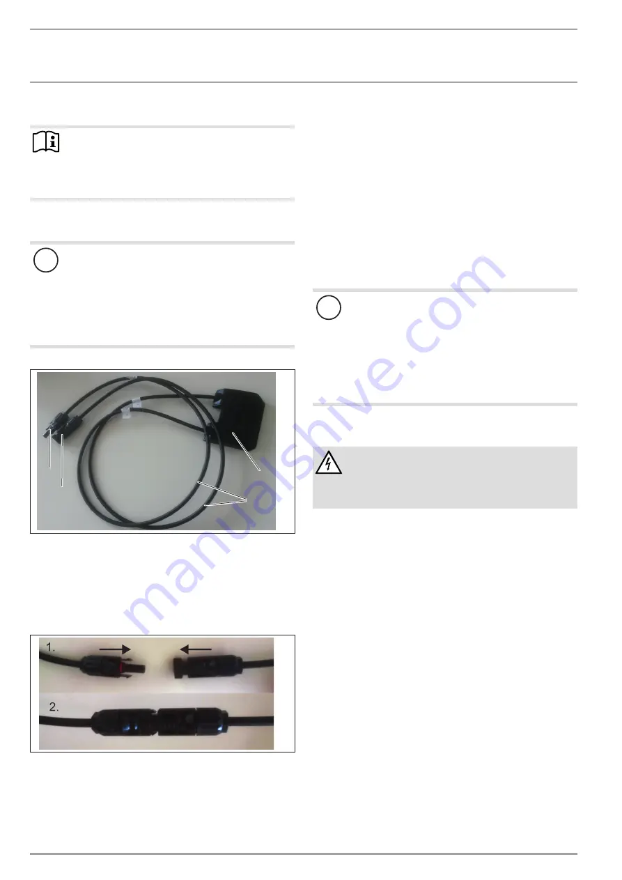
The switch panel is located at the back of the module:

D

00000

45

21

2

2

4

1

3

1  Switch panel
2  Connecting cables
3  Socket
4  Plug


f

Remove the plug and socket from the retainer.


f

Connect the plug of this module with the socket of the next 
module.

D

00000

45

21

3


f

Lock the plug inside the socket by turning it 90° as far as it 
will go.


f

Connect the plug or socket of the first and last module in the 
electrical line to the inverter cable.

6.2.2  Earth

You can secure an earth cable via the holes in the frame (see 
chapter "Specification"/"Dimensions").

7.  Maintenance

The modules are low-maintenance. We recommend an annual 
visual inspection. 


f

Also check the mechanical and electrical connections for 
damage.

Dirt on the modules reduces the output and yield. If the modules 
are installed at an angle of inclination of more than 15°, rain is 
generally sufficient to clean them.

!


Damage to the appliance and environment

To avoid damage caused by scratching or high tempera-

ture differentials:


f

Use exclusively liquid neutral cleaning agents to 

clean modules.


f

Never use scouring or abrasive cleaning agents.


f

Only use water matched to the temperature of the 

module surface.


f

Wipe the module surface with water and a soft 

cloth.

8.  Dismantling


DANGER Electrocution

Never disconnect any connections under load.

Make sure there is sufficient protection against contact 

with live components.


f

Only use insulated tools.

To make the photovoltaic system load-free: 


f

Isolate the inverter from the mains on the AC side.


f

Disconnect the photovoltaic system from the inverter at the 
disconnect point on the DC side.


f

Ensure that there is no electrical voltage in the system.


f

Dismantle the photovoltaic system in reverse order to its in-
stallation. Observe all safety instructions.

Содержание 274178

Страница 1: ...UND INSTALLATION OPERATION AND INSTALLATION UTILISATION ET INSTALLATION KEZEL S S TELEP T S PHOTOVOLTAIK MODUL PHOTOVOLTAIC MODULE MODULE PHOTOVOLTA QUE NAPELEM MODUL TEGREON 255 P TEGREON 260 P TEGR...

Страница 2: ...gemeine Hinweise Das Kapitel Betrieb richtet sich an den Anlagenbetreiber und den Fachhandwerker Das Kapitel Installation richtet sich an den Fachhandwerker Hinweis Lesen Sie diese Anleitung vor dem G...

Страница 3: ...tigen Bohren Sie keine L cher in den Modulrahmen oder in die Glasoberfl che bohren und f hren Sie keine Schwei arbeiten an oder in unmittelbarer N he der Module aus GEFAHR Verletzung F r den gesamten...

Страница 4: ...m Material bestehen 6 1 Modul an das Gestell klemmen Eine Klemmung der Module ist an den langen und kurzen Rah menseiten im zugelassenen Klemmbereich siehe Technische Daten Ma e erlaubt Montieren Sie...

Страница 5: ...Wechselrichter an 6 2 2 Erdung Eine Erdungsleitung k nnen Sie an den Bohrungen im Rahmen befestigen siehe Kapitel Technische Daten Ma e 7 Wartung Die Module sind wartungsarm Wir empfehlen eine j hrli...

Страница 6: ...WWW STIEBEL ELTRON COM INSTALLATION Technische Daten 9 Technische Daten 9 1 Ma e 5 2 40 989 5 2 1134 260 1654 260 5 2 5 2 40 mm 13 8 mm 247 115 100 200 50 6 000 Pa 4 200 Pa 2 400 Pa D0000045221 i30 Kl...

Страница 7: ...tung bei 800 W m2 NOCT AM 1 5 PMPP W 189 6 193 4 197 3 Spannung bei 800 W m2 NOCT AM 1 5 UMPP V 28 56 28 80 28 90 Leerlaufspannung bei 800 W m2 NOCT AM 1 5 UOC V 35 58 35 89 36 20 Strom bei 800 W m2 N...

Страница 8: ...tung unter STC Standard Test Conditions die wie folgt definiert sind Strahlungsleistung von 1 000 W m bei einer spektralen Dich te von AM 1 5 und einer Zelltemperatur von 25 C und aus schlie lich mit...

Страница 9: ...tet Garantieleistungen au erhalb der Bundesrepublik Deutschland zu erbringen Bei St rungen eines in Deutschland er worbenen aber in anderen Staaten eingesetzten Ger tes ist dieses ggf auf Gefahr und K...

Страница 10: ...ht nach den rtlich geltenden Vorschriften und Gesetzen UMWELT UND RECYCLING Soweit Sie von dem Mitarbeiter aufgefordert werden ihm im Ge spr ch n her bestimmte Kaufunterlagen zuzusenden sind diese pos...

Страница 11: ...YCLING OPERATION 1 General information The chapter entitled Operation is intended for the operator and the heating contractor The chapter Installation is intended for heating contractors Note Read the...

Страница 12: ...s in the module frame or the glass surface and never carry out any welding work on or directly near to the modules DANGER Injury A second person who can provide help in the event of a possible acciden...

Страница 13: ...and weather resistant material 6 1 Clamping the module to the frame The modules may only be clamped to the long and short frame sides in the permitted clamping area see Specification Dimensions When u...

Страница 14: ...e electrical line to the inverter cable 6 2 2 Earth You can secure an earth cable via the holes in the frame see chapter Specification Dimensions 7 Maintenance The modules are low maintenance We recom...

Страница 15: ...BEL ELTRON COM TEGREON 15 INSTALLATION Specification 9 Specification 9 1 Dimensions 5 2 40 989 5 2 1134 260 1654 260 5 2 5 2 40 mm 13 8 mm 247 115 100 200 50 6 000 Pa 4 200 Pa 2 400 Pa D0000045221 i30...

Страница 16: ...800 W m2 NOCT AM 1 5 PMPP W 189 6 193 4 197 3 Voltage at 800 W m2 NOCT AM 1 5 UMPP V 28 56 28 80 28 90 Idle voltage at 800 W m2 NOCT AM 1 5 UOC V 35 58 35 89 36 20 Current at 800 W m2 NOCT AM 1 5 IMPP...

Страница 17: ...only be issued by those subsidiaries Such warranties are only granted if the subsidiary has issued its own terms of warranty No other warranty will be granted We shall not provide any warranty for app...

Страница 18: ...apitre Exploitation s adresse aux exploitants de l instal lation et aux installateurs Le chapitre Installation s adresse aux installateurs Remarque Veuillez lire attentivement cette notice avant utili...

Страница 19: ...le module Ne pas marcher sur le module Ne pas utiliser de modules endommag s S assurer qu aucun autre composant de l installation ne per turbe les modules de mani re m canique ou lectrique Ne pas per...

Страница 20: ...essoires adapt s votre module Pour la mise en service du module vous aurez besoin des accessoires suivants Ch ssis Onduleur Compteur d injection Sectionneur CC 5 Travaux pr paratoires 5 1 Lieu d impla...

Страница 21: ...utilis s sur des syst mes librement accessibles avec une tension CC sup rieure 50 V ou une puissance sup rieure 240 W DANGER lectrocution Ne d connectez aucune connexion sous charge lec trique Veillez...

Страница 22: ...envi ronnement Pour viter tout endommagement d aux rayures ou aux importantes variations de temp rature f f nettoyez uniquement avec un produit neutre f f N utilisez pas de produit de nettoyage r cure...

Страница 23: ...LTRON COM TEGREON 23 INSTALLATION Donn es techniques 9 Donn es techniques 9 1 Dimensions 5 2 40 989 5 2 1134 260 1654 260 5 2 5 2 40 mm 13 8 mm 247 115 100 200 50 6 000 Pa 4 200 Pa 2 400 Pa D000004522...

Страница 24: ...M 1 5 Puissance 800 W m2 NOCT AM 1 5 PMPP W 189 6 193 4 197 3 Tension 800 W m2 NOCT AM 1 5 UMPP V 28 56 28 80 28 90 Tension en circuit ouvert 800 W m2 NOCT AM 1 5 UOC V 35 58 35 89 36 20 Courant 800 W...

Страница 25: ...telle garantie ne pourra cependant tre accord e que si la filiale a publi ses propres conditions de garantie Il ne sera accord aucune garantie par ailleurs Nous n accordons aucune garantie pour les ap...

Страница 26: ...EL S 1 ltal nos tudnival k Az zemeltet s fejezet az zemeltet s a szakszerel k r sz re k sz lt A Telep t s fejezet a szakszerel k r sz re k sz lt Tudnival Haszn lat el tt olvassa el gondosan ezt az tmu...

Страница 27: ...mechanikai vagy elektromos hat ssal a modulra Tilos furatot f rni a modulkeretbe vagy az vegfel letre va lamint hegeszt si munk latokat v gezni a modul k zvetlen k zel ben S r l svesz ly A szerel shez...

Страница 28: ...et l sd M szaki adatok M retek A bilincses r gz t s eset n biztos t sk nt r gz tsen csavarokkal egy lecs sz sg tl t a modulok legals sor hoz Tudnival f f Ehhez vegye figyelembe az llv nyzat telep t si...

Страница 29: ...egyszer szem rev telez ses ellen rz s v grehajt s t aj nljuk f f Ennek sor n ellen rizni kell a g p szeti s elektromos csatla koz kat is az esetleges meghib sod sok szempontj b l A modulokra rak dott...

Страница 30: ...tm ny t r shat r max norm l zemben 3 3 3 N vleges fesz lts g norm l zemben UMPP V 30 64 30 90 31 16 resj rati fesz lts g norm l zemben UOC V 37 45 37 78 38 12 N vleges ramer ss g norm l zemben IMPP A...

Страница 31: ...sug rz si teljes tm ny AM 1 5 spektr lis s r s g s 25 C cellah m rs klet mellett Garancia A N metorsz gon k v l v s rolt k sz l kekre nem rv nye sek c g nk n metorsz gi v llalatainak garanci lis felt...

Страница 32: ...fo stiebel eltron dk www stiebel eltron dk Finland STIEBEL ELTRON OY Kapinakuja 1 04600 M nts l Tel 020 720 9988 info stiebel eltron fi www stiebel eltron fi France STIEBEL ELTRON SAS 7 9 rue des Sell...

Отзывы: