Installation procedure
Proximity reader - Model LXS R21 (Wiegand and Clock & Data)
© STId 2009 – NI017A04 - Ed. 21/09/2009
1
••••
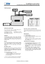
Wiring diagram :
R21 series
(ISO 2x)
R21 series
(ISO 3C)
0
0V
0V
1
+12 VDC
+12 VDC
2
Code
Code
3
Data
Data
4
Clock
Clock
5
Mode / Scan
Mode
6
Red Led
Red Led
7
Green Led
Green Led
2
••••
Recommended cables:
Use a multi-conductor cable, pair shielded. When power is
supplied with the same cable we recommend:
1 pair AWG24 for up to 30 m
1 pair AWG35 for up to 50 m
2 pairs AWG24 for up to 60 m
2 pairs AWG35 for up to 100 m
3 pairs AWG24 for up to 100 m
3
••••
Buzzer
The buzzer gives an indication of correct read, not depending
on the eventual authorizations or access rights given to a card.
It will emit a brief sound as soon as a card or tag is read. It is
possible to shut it off by removing the jumper located just
nearby the buzzer.
4
••••
Led
The led is bicolor (red & green). When the reader is powered
on, it is amber (red+green). It can be driven by the remote
system to light it either red or green, by bringing a 0V
respectively on the red or green inputs of the reader’s
connector.
5
••••
« Mode » input
By default, when this input is not connected, the reader will
automatically delay the transmission of the code every 2
seconds when a card is left in the reading field. If a new card is
shown to the reader before this time laps, its code will be
transmitted immediately.
If you want to activate or deactivate the delay:
1. Power off the reader.
2. Connect the input Mode to 0V to deactivate the delay.
Do not connect the input mode to activate the delay.
3. Power on the reader.
⇒
Check if the reader is operating properly by presenting a
card. The reader should then beep quickly on each reading.
5
••••
« Scan » input – 2L protocol only
This input allows deactivating the RF field which stops card
detections. To deactivate the RF field connect the input “Scan”
to 0V.
6
••••
Installation
e)
Connect the reader
f)
Test the reading and communication.
g)
Attach the reader on the wall, or on standard electrical
flush-boxes. Install the screw caps.
Caution: Screw caps are made to be hard to remove
once installed. We recommend making all the tests
before installing them.
7
••••
Precautions for installation
•
Power supply tension at the reader’s connector should be
strictly comprised between 10.5V and 15V.
•
Keep the reader away from computer or power cables as
much as possible. They can generate an electrical
perturbation that is function of their proximity and
radiation level.
•
Distance to respect between two readers : parallel plan :
30 cm – Same plan : 40 cm – Perpendicular : 25 cm.
•
If the reader is mounted on a metallic surface it can affect
the reading distance. To get the maximum reading
distance, the reader should be installed at no less than 7
cm from any metallic surface.
Power
12V / 0,5A min.
Data signals
LEDS commands
JUMPER
Non fitted : Buzzer deactivated
Fitted : Buzzer activatd
0 1
2
3 4
5 6
7


