Page 2 of 4
INSTALLATION GUIDE • SERIES 44+ MODULAR FLOOR GRID SYSTEM
ZIS1049 0916
PREPARATION
Orientation: Grids are designed to be installed with slots running parallel to cable pathway or support systems
such as vertical cable trays or racks (Fig 3).
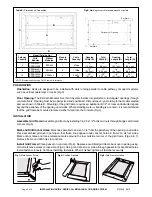
Floor Opening: The EZ-Path Modular Floor Grid System installs into preformed, rectangular openings through
concrete floors. Opening must be properly sized and positioned. Dimensions vary according to the model selected
and are shown in Table B. Mounting of the grid frame requires an additional 2-1/2” of clear unobstructed space
beyond the periphery of the opening on all sides. Where standing water or flooding is a concern, it is recommended
that the grid frame be mounted to raised curbs formed into the concrete (Fig 4).
INSTALLATION
Assemble Grid Frame: Assemble grid frame by installing 1/4-20 x 1/2” bolts and nuts through flanges at mitered
corners (Fig 5).
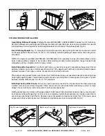
Mark and Drill Anchor Holes: Mark lines parallel to and an 1-1/4” from the periphery of the opening on all sides.
Place assembled grid over opening so that these lines appear under anchor holes in frame on all four sides.
Mark anchor holes and trace reference marks around the four outside corners of the grid frame (Figs 6 & 7).
Remove frame and drill holes for anchors.
B
C
D
A
PeripheryofOpening
1-1/4"
RefMark
RefMark
Pathway
Capacity
Model (Catalog No.)
Module
Capacity
Cable
Capacity*
Opening
Width (A)
Total
Width (C)
Opening
Length (B)
Total
Length (D)
With
Modules
Without
Modules
4
EZDG444S /
EZDG444S2
EZG444
1
875+
6”
(15.3 cm)
11”
(28 cm)
18”
(45.7 cm)
23”
(58.4 cm)
8
EZDG844S /
EZDG844S2
EZG844
2
1750+
12”
(30.5 cm)
17”
(43.2 cm)
18”
(45.7 cm)
23”
(58.4 cm)
16
EZDG1644S /
EZDG1644S2
EZG1644
4
3500+
24”
(61 cm)
29”
(73.7 cm)
18”
(45.7 cm)
23”
(58.4 cm)
NOTE: *Nominal capacity using Cat 5E cables for reference.
Table B: Dimensions & Capacities
Fig 6: Marking corner reference and anchor points
Fig 7: Mark Anchor Points
Fig 8: Position Gaskets
Fig 9: Grid Frame Installed
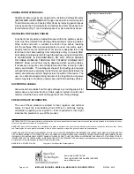
Install Grid Frame: Place gasket on concrete (Fig 8). Replace assembled grid frame back over opening using
corner reference marks to reposition (Fig 9). Using concrete screw, probe through gasket to locate drilled holes.
Install fastener loosely. Continue installing fasteners. When finished, tighten all fasteners securely.


