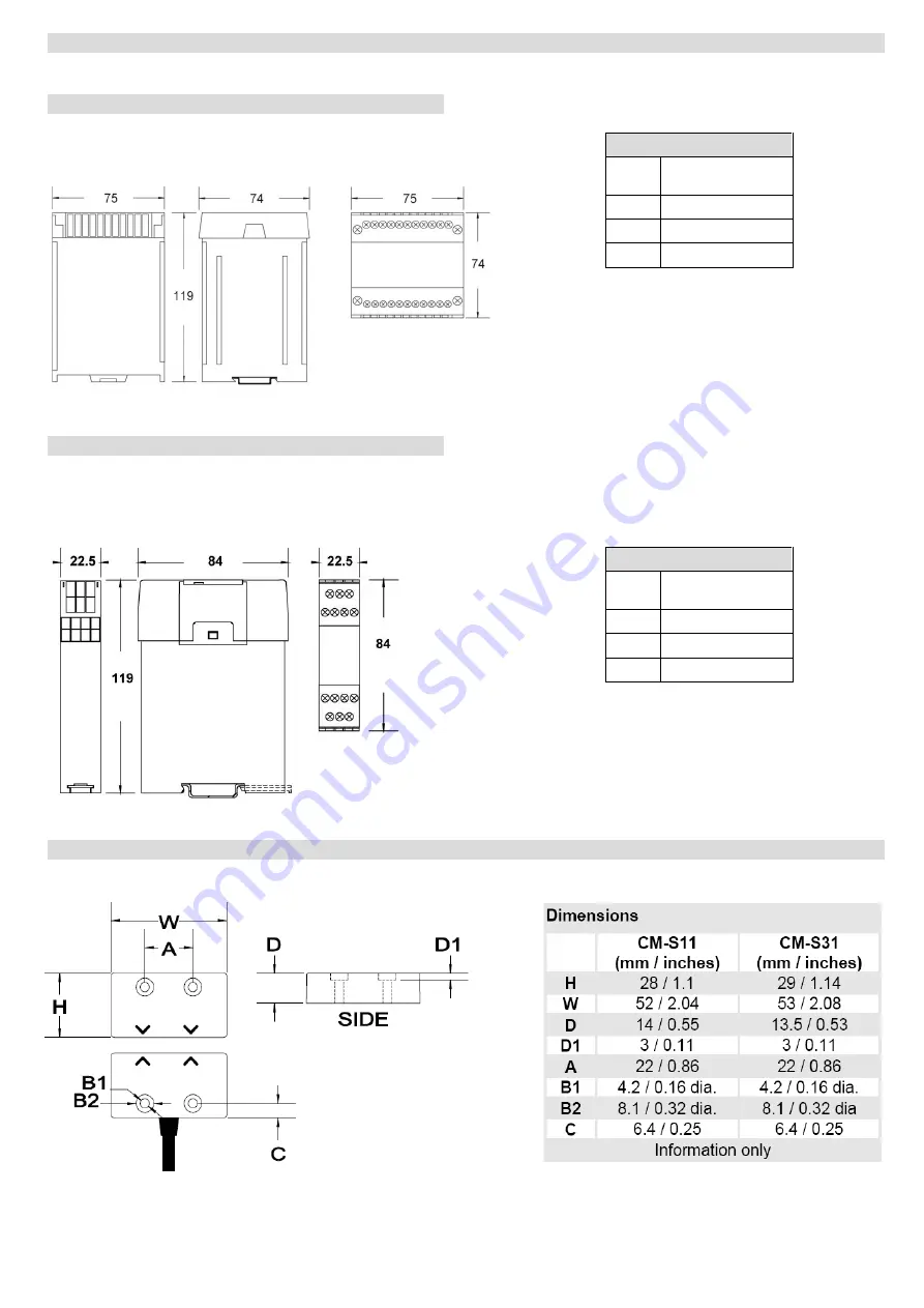
Dimensions
CM-S41 (ALL VOLTAGES)
CM-S21 / CM-SE
CM-SERIES SAFETY SWITCHES
CM-S41
(mm/inches)
W
75 / 2.95
H
74 / 2.91
D
119 / 4.68
CM-S21 & CM-SE
22.5 / 0.88
84 / 3.3
Страница 1: ...rd switch is shown by the YELLOW LEDs Additional CMS E extender modules can be added to monitor larger systems Safety Switches The CM Series safety switches are non contact tamper resistant safety switches Resin encapsulated into an ABS or Stainless Steel case providing environmental protection to IP67 the switches can withstand most conditions including water dust and high pressure hose cleaning ...
Страница 2: ...ly be assembled to monitor 30 machine guards while retaining the high control category performance required in many applications SIL3 PLe according to EN ISO 62061 EN ISO 13849 1 To assemble the system mount the control unit in a suitably IP rated control panel Min IP54 and fix the safety switches to the gates as shown Connect the safety switches to the control unit Using the appropriate selection...
Страница 3: ...otection if required and terminate into the appropriate control unit input channel Follow the color coding of the wires to the labels on the control unit input terminals I e BLUE wire to BL and DRAIN wire to DR IMPORTANT Use the GATE inputs in sequence Examples One Guard System Use input 1 on the CM S21 Or input 1 on the CM S41 if E Stop function required Three Guard System Use inputs 1 2 3 on the...
Страница 4: ...e auxiliary N C contact 31 32 External fusing is recommended EMERGENCY STOP MONITORING Dual channel emergency stop buttons and or mechanical safety switches can be monitored using the S13 S14 S23 S24 circuits If this feature is not used link terminals S13 to S14 and S23 to S24 OPERATION When power is applied to the control module the RED Power LED will illuminate The GREEN De select indicators wil...
Страница 5: ...vely guided contacts for K1 K2 if monitoring is required CONTROL CONTACTS Two sets of positively guided N O safety contacts on terminals 13 14 and 23 24 rating 4 Amps One auxiliary N C contact 31 32 External fusing is recommended OPERATION When power is applied to the control module the RED Power LED will illuminate The number of inputs selected must match the number of guard switches otherwise th...
Страница 6: ...d will illuminate The number of inputs selected must match the number of guard switches otherwise the control unit will not operate The YELLOW Guard status indicators will be illuminated if the guard is closed or be permanently on if the guard is de selected If all the monitored machine guards are closed and the RE SET button is pressed and released on the main control unit the control relays will...
Страница 7: ...Dimensions CM S41 ALL VOLTAGES CM S21 CM SE CM SERIES SAFETY SWITCHES Dimensions CM S41 mm inches W 75 2 95 H 74 2 91 D 119 4 68 Dimensions CM S21 CM SE mm inches W 22 5 0 88 H 84 3 3 D 119 4 68 ...
Страница 8: ...esistance Amplitude 2mm frequency 10 to 55 Hz Enclosure protection Housing IP40 Terminals IP20 IP67 Switching distance 5 7mm ON 8 12mm OFF Minimum gap Minimum gap Operating temperature 10C to 55C 85 Humidity max 10C to 55C Housing material Polycarbonate Red ABS Red 316 Stainless Steel Mounting Fixing 35mm Symmetric DIN Rail 22mm Centres M4 security screws supplied Safety Related Data PL in accorda...