background image

10

INSTALL 7 

CAPACITORS

5

1u

+

1u

+

+

100u

+

10

u

+

100u

+

100u

1u

+

1u

+

1u

+

+

10

u

100pF

22n

22n

22n

22n

22n

22n

220n

2n2

1n

100n

100n

100n

100n

100n

100n

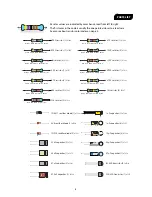
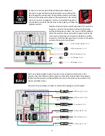
.0022µF capacitor (1) 

#7324

.22µF capacitor (1) 

#7305

.1µF capacitor (6) 

#7304

100pF capacitor (1) 

#7326

101J

100V

.001µF capacitor (1) 

#7302

102J

2n2J630

.022µF capacitor (6) 

#7317

.1J63

.22J63

1µF capacitors (5) 

#7314


1uF

10µF capacitor (2) 

#7338

100µF capacitor (3) 

#7312


10uF

100uF

10K

1M

470K

100K

22K

1K

47K

220K

10K

10K

10K

10K

10K

10K

10K

470K

22K

47K

47K

220K

22K

4K7

10K

1M

470K

100K

22K

1K

47K

220K

10K

10K

10K

10K

10K

10K

10K

470K

22K

47K

47K

220K

22K

4K7

22nJ

47

n

J

22

n

J

47

n

J

33

n

J

10uF

47

4J

100v

33

nJ

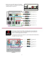
33nF capacitor (1)

#7475

22nF capacitor (2)

#7317

470nF capacitor (1)

#7336

22

nJ

M

MK

BH
8

50

-

47n

J

47nF capacitor (2)

#7307

M

MK

BH
N

50

-

102J

1nF capacitor (1)

#7302

TL071

INSTALL THE 

OP-AMP

6

2n2J630

TL072

TL071

PT2399

PT2399

PT2399 

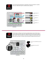
echo audio 

processor (1)


#7490


TL071 low noise distortion op-amp (1)

#7509


Integrated circuit socket (1)

#7484


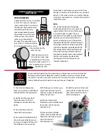
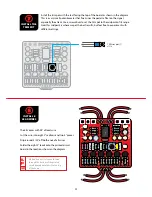
The remaining capacitors below are not polarized. However, best practice is to solder 
these caps in place all facing the same direction when possible. 

On the printed circuit board, note the marking for the integrated circuit socket: there is 
a solid rectangle printed at one end. The socket itself has a notch at one end. Solder the 
socket in place, with the notched end toward the rectangle on the board. Plug in the op-
amp, with the small dot on the op-amp oriented toward the notched end of the socket.

2n2J630

TL072

TL071

PT2399

PT2399

PT2399 

echo audio 

processor (1)


#7490


TL071 low noise distortion op-amp (1)

#7509


Integrated circuit socket (1)

#7484


Содержание SWELL DRIVE

Страница 1: ...ced but we have found a stash that enables us to offer these kits When they re gone they re gone POWER This pedal requires a standard 9V DC center negative power supply not included and consumes less than 100mA There s no battery option TECHNICAL SUPPORT If you have any questions before during or after this project please do not hesitate to reach out to our Tech Support Team They are available by ...

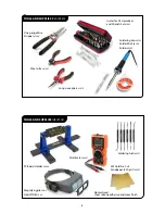
Страница 2: ...lder 0505 Wire Cutter 1607 Long nose pliers 1610 Fine gauge Wire Stripper 1606 Guitar Tech Screwdriver and Wrench Set 3693 Not pictured Clear silicone adhesive and spray finish PC Board Holder 0500 Magnifying glass or OptiVISOR 1685 Soldering Aids 0521 Multimeter 3607 3M Gold Fre Cut Sandpaper 220 grit 5097 ...

Страница 3: ...ow Violet Black Orange Brown 1M resistor 4 7367 Brown Black Black Yellow Brown 22K resistor 3 7379 Red Red Black Red Brown 33µF capacitor 1 7477 3 3uF 33nF capacitor 1 7475 33nJ BC549 transistor 5 7510 BC549 C J23 2SK30A transistor 1 7517 K30A GR7L 22nF capacitor 2 7317 22nJ 47nF capacitor 2 7307 47nJ 1nF capacitor 1 7302 102J 1N914 rectifier diode 3 7521 5V6 rectifier diode 1 7520 1N5817 rectifie...

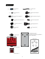
Страница 4: ... square 4 7560 5mm LED mounting bezel 1 7432 TL071 low noise distortion op amp 1 7509 Integrated circuit socket 1 7484 Control knob 2 7501 08 EDT 2 1mm DC power jack 1 7468 PARTS LIST CONT ATTACK S ENSITIVIT Y 1 4 mono jack 2 4652 Printed circuit board 1 Sticker sheet 1 Breakout board 1 IN GND SW OUT Pre drilled enclosure top 1 Pre drilled enclosure bottom not pictured 1 Screws not pictured 4 ...

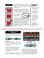
Страница 5: ...5 100 000 5 BLUE 6 6 6 1 000 000 25 VIOLET 7 7 7 10M 1 GRAY 8 8 8 01 SILVER WHITE 9 9 9 1 GOLD 0 SOLDERING MORE HELPFUL SOLDERING TIPS AND TRICKS Keep your soldering tip clean by wiping it often on a damp sponge Also keep it tinned by occasionally melting a little solder onto it Don t blow on the hot solder or touch anything until the joint has cooled completely A good solder joint is shiny a sign...

Страница 6: ...ed in farads refers to how much electricity a capacitor can hold One farad 1F would be much too large for use in a pedal Caps for pedals are rated between millionths of a farad called microfarads μF billionths of a farad 1 0 1 J 1 0 0 V 102J 1u F 1J63 UNDERSTANDING ELECTRONIC COMPONENTS INTEGRATED CIRCUITS Integrated circuits are tiny and complex complete circuits containing many components Their ...

Страница 7: ...f the LED will be shorter and the cathode side of the LED housing will be flat LEDs are mounted inside of a bezel which protects the LED and insulates the leads from shorting against the enclosure or any internal components UNDERSTANDING ELECTRONIC COMPONENTS PAINTING YOUR PEDAL ENCLOSURE 1 1 To minimize redoing steps make sure you have a solid idea of the look and feel you re going for 2 Lightly ...

Страница 8: ...ponents is the correct side In some cases components must be inserted into the printed circuit board in a specific direction due to their polarity so follow the graphics carefully Note the stripe around one end of each diode This marks the negative lead On the printed circuit board the printed outline of the diode also shows this stripe Install the diode to match the direction shown and solder in ...

Страница 9: ...n 470K resistor 2 7382 Yellow Violet Black Orange Brown 22K resistor 3 7379 Red Red Black Red Brown 100K resistor 3 7365 Brown Black Black Orange Brown 1M resistor 4 7367 Brown Black Black Yellow Brown INSTALL 11 CAPACITORS 4 1uF 10uF 10uF 1uF 1uF 1uF 1uF 10uF 1uF 1uF 10uF 10µF capacitor 3 7338 33µF capacitor 1 7477 10uF 33uF 47µF capacitor 1 7478 47uF 1µF capacitor 6 7337 1uF 10uF Resistors have ...

Страница 10: ... capacitor 1 7336 22nJ MMK BH8 50 47nJ 47nF capacitor 2 7307 MMK BHN 50 102J 1nF capacitor 1 7302 TL071 INSTALL THE OP AMP 6 2n2J630 TL071 PT2399 PT2399 PT2399 echo audio processor 1 7490 TL071 low noise distortion op amp 1 7509 The remaining capacitors below are not polarized However best practice is to solder these caps in place all facing the same direction when possible On the printed circuit ...

Страница 11: ...t feel free to experiment with different settings 08 EDT 10uF 10K trim pot 1 7570 08 EDT 22nJ 47nJ 22nJ 47nJ 33nJ TL071 1uF 10uF 10uF 1uF 1uF 1uF 1uF 08 EDT 10uF 1uF INSTALL 8 LEAD WIRES 8 The kit comes with 24 of lead wire Cut the wire into eight 2 sections and two 4 pieces Strip around 3 32 off both ends of all wires Solder the eight 2 leads onto the printed circuit board in the locations shown ...

Страница 12: ...facing up reading left to right Slide the lugs of the footswitch up through the bottom of the board If the lugs of the footswitch don t quite fit in the breakout board use a pair of pliers to gently bend the lugs of the footswitch until the breakout board slides over the lugs Solder each lug to the corresponding breakout board eyelet IN GND SW OUT IN G ND SW OUT You can use the pedal enclosure as ...

Страница 13: ...e back of the pots from the soldered leads of the other parts on the printed circuit board Once you ve removed any index pins and added the foam tape to the back of each pot use the pedal enclosure as a mount for the control pots while you solder the printed circuit board to them Just lay the enclosure face up and arrange the pots in their holes No need to fasten them with a nut from the back if y...

Страница 14: ...er than the positive The printed circuit board is held in place by the control pots but the LED leads need to pass through their eyelets in the printed circuit board before the pots will pass through the enclosure Pass the longer positive lead of the LED through the eyelet marked A and the shorter negative lead through the eyelet marked K Next secure the pots by installing their shafts through the...

Страница 15: ...the washer and thread the nut onto the shaft enough so that the pot can rotate freely You may need to rotate the jack to provide easier access to setting the solder joints Solder the left most wire at the top of the printed circuit board to the input jack lug that corresponds with the sleeve connection The sleeve lug should be the one closer to the DC jack Solder the 4 wire on the left side of the...

Страница 16: ... the sleeve connection The sleeve lug should be the one closer to the DC jack Solder the 4 wire on the right side of the breakout board to the lug of the output jack that corresponds with the tip connection The tip lug should be the one closer to the outside wall of the enclosure Once the solder has cooled orient the jack as shown in the diagram making sure none of the connections on the jack are ...

Страница 17: ...ot filter dirty power as well and let through unwanted noise Do not run at higher voltages Current draw is 25mA SENSITIVITY Controls the decay of the effect With a low sensitivity setting you will have to wait longer for the sound to decay before playing another note will evoke the swell effect ATTACK Controls how fast the sound swells after the signal hits the circuit of the pedal A lower attack ...

Отзывы: