background image

1.  SETUP AND MOVING

2

2

5

5

7

7

1

9

8

11

15

11

8

6

14

14

SETUP AND MOVING 

3

AVENGERS INFINITY QUEST PRO MANUAL 500-55R1-01

© MARVEL

1.1  FIRST-TIME 

SETUP INSTRUCTIONS

CAUTION: AT LEAST TWO (2) 

PEOPLE ARE REQUIRED TO 

MOVE AND MANEUVER THE 

GAME. USE PROPER MOVING 

EQUIPMENT AND EXTREME 

CARE WHILE HANDLING. STERN 

PINBALL MACHINES WEIGH 

OVER 250LBS BOXED.

TOOLS REQUIRED

• 

5/8” Socket Wrench

• 

Utility Knife

• 

Snips

• 

An Assistant

Your brand new Stern Pinball Machine is 

carefully packed for safety and security. 

For your safety, exercise caution and use 

the correct tools and sufficient help when 

setting up your new game. 

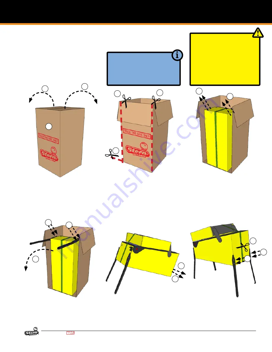
1.  Locate the side labeled “TRUCK 

THIS SIDE ONLY”. The bottom of 

the game faces this side.

2.  Open the top box flaps by pulling 

hard in an upward motion on each 

flap. If the flaps are taped, cut the 

tape first, taking care to avoid the 

box staples.

3.  Remove the four (4) foam pieces 

and two (2) narrow box tubes 

which contain the four (4) identical 

legs with levelers.

4.  DO NOT CUT STRAPPING YET. 

Keep backbox secured in the 

down position.

5.  With the utility knife, carefully cut 

down the left and right corners of 

the box. 

6.  Let the face fall forward and 

remove the entire side by carefully 

cutting the bottom.

7.  With the game still in its folded po-

sition, use a ⅝” wrench to loosen 

and remove the 2 leg bolts on each 

side of the front cabinet. Ensure 

the leg levelers are screwed all the 

way into the legs.

8.  Install front legs using the bolts 

removed from the cabinet. Secure 

tightly.

9.  Have someone help you carefully 

set the game down on the front 

legs.

10.  Set aside the open box.

11.  With a ⅝” socket wrench, loosen 

and remove the 2 leg bolts on 

each side of the rear cabinet, 4 

total.

12.  Using supports or two people, 

prop the rear of the cabinet up. 

13.  Ensure the rear leg levelers are 

screwed all the way into the legs.

14.  Install rear legs using the 4 bolts 

removed from step 11.

Содержание Avengers Infinity Quest

Страница 1: ...Grove Village Illinois USA Stern Pinball has inspected each game element to ensure it meets our quality standards Each pinball machine has unique characteristics that make it a one of a kind American...

Страница 2: ...ower Distribution Board 37 4 21 Power Plug Wiring 37 5 Parts Reference 38 5 1 Playfield Rubber Parts 38 5 2 Rubber Size Chart 38 5 3 Playfield Assemblies Top 39 5 4 Playfield Assemblies Bottom 40 5 5...

Страница 3: ...he box staples 3 Remove the four 4 foam pieces and two 2 narrow box tubes which contain the four 4 identical legs with levelers 4 DO NOT CUT STRAPPING YET Keep backbox secured in the down position 5 W...

Страница 4: ...box lid and retaining clip for future use 24 Locate the two 2 backbox bolts in the cash box 25 Carefully raise backbox to upright position while ensuring that cables are not pinched 26 Use the wrench...

Страница 5: ...mmended 6 5 pitch Playfield angles greater than 6 5 can be achieved by turning out the rear leg level er s for increased difficulty and faster gameplay 3 Use a pinball to roll down the center of the p...

Страница 6: ...T 20 000 000 6 DYNAMIC REPLAY START 60 000 000 7 REPLAY LEVEL 1 15 000 000 8 REPLAY LEVEL 2 30 000 000 9 REPLAY LEVEL 3 45 000 000 10 REPLAY LEVEL 4 60 000 000 11 REPLAY BOOST YES 12 SPECIAL LIMIT 1 1...

Страница 7: ...ed follow the remaining steps 2 REMOVE THE LEGS AND STAND UP 1 3 TRANSPORTING THE GAME 2 3 4 6 Remove the legs rear legs first Use a stool or a friend to support the rear of the game 7 Rest the rear o...

Страница 8: ...s for free operation Visual check for loose or broken playfield and cabinet parts and repair as necessary Electrical check Plug into grounded outlet and check for proper operation through DIAGNOSTICS...

Страница 9: ...P protocols or signaling stan dards SPIKE nodes are not compatible with standard computer networking equipment CAUTION Plugging a SPIKE Node or CPU board into a standard Ethernet port may damage one o...

Страница 10: ...device has a common 48V power source that is then connected to ground by a dedicated control transistor Each driver is protected against shorting static elec tricity and over current conditions Take...

Страница 11: ...dle Center LED Board Playfield 520 8483 00 Node 9 OFF OFF ON OFF Playfield 48V Core Driver Node Playfield 520 7017 72 9a n a Top Center LED Board Playfield 520 8472 00 9a1 n a Top LT LED Board Playfie...

Страница 12: ...Motor 1 CN16 1 BLU 48V 5 RED Cabinet Motor 1 DR 0 041 5029 04 8 Up Left Flip 8 CN7 3 YEL BLK 48V 1 GRY ORG Playfield Coil 22 1080 8 DR 6 090 5032 ND 9 10 3 Bank Drop 8 CN7 2 YEL RED 48V 1 GRY ORG Pla...

Страница 13: ...SPIKE SYSTEM AND NODE GUIDE 13 AVENGERS INFINITY QUEST PRO MANUAL 500 55R1 01 MARVEL Figure 3 2 1 Playfield driver locations top view DRIVER REFERENCE CONTINUED...

Страница 14: ...Trough 3 8 8a CN14 Playfield Opto 8 SW 35 520 5344 00 tx 520 8509 00 rx 19 Trough 2 8 8a CN14 Playfield Opto 8 SW 36 520 5344 00 tx 520 8509 00 rx 20 Trough 1 8 8a CN14 Playfield Opto 8 SW 37 520 534...

Страница 15: ...ght Ramp Exit Opto 9 CN12 3 WHT RED 10 BLK WHT Playfield Opto 9 SW 9 515 0215 00 tx 515 0215 01 rx 59 Inner Loop Opto 9 CN12 4 WHT ORG 10 BLK WHT Playfield Opto 9 SW 10 515 0215 00 tx 515 0215 01 rx 6...

Страница 16: ...0 97 ANGLE SENSOR 9 8 c Playfield Mag Angle 8 SW 49 520 8466 00 98 ANGLE SENSOR WEAK 8 c Playfield Mag Angle 8 SW 50 520 8466 00 99 ANGLE SENSOR THRESH OLD 8 c Playfield Mag Angle 8 SW 51 520 8466 00...

Страница 17: ...SPIKE SYSTEM AND NODE GUIDE 17 AVENGERS INFINITY QUEST PRO MANUAL 500 55R1 01 MARVEL SWITCH REFERENCE CONTINUED Figure 3 3 1 Playfield switch locations top view...

Страница 18: ...te 8 LP 16 520 8477 00 24 Black Widow Collect 8 b LED8 Playfield Feature White 8 LP 15 520 8477 00 25 Thor Collect 8 b LED7 Playfield Feature White 8 LP 14 520 8477 00 26 Black Panther Collect 8 b LED...

Страница 19: ...Playfield Feature RGB 9 LP 81 520 8475 00 78 S T RANGE G 9 b LED16 Playfield Feature RGB 9 LP 82 520 8475 00 79 S T RANGE B 9 b LED16 Playfield Feature RGB 9 LP 83 520 8475 00 80 ST R ANGE R 9 b LED18...

Страница 20: ...d Feature RGB 9 LP 15 520 8471 00 131 Skill Shot Rollover 9 CN14 6 BRN GRN 7 8 YEL Playfield Feature White 9 LP 3 520 6824 0x 132 133 134 Marvel Gem R 8 d CN3 2 RED BRN 1 RED Playfield Feature RGB 8 L...

Страница 21: ...6 00 184 ANGLE SENSOR ENABLE 8 c Playfield Digital Out 8 LP 27 520 8466 00 185 186 187 Coin Door GI 1 CN5 2 YEL 1 YEL WHT Coin Door G I White 1 LP 1 112 5033 08 188 Bottom GI Left x7 8 CN15 5 WHT BLK...

Страница 22: ...22 SPIKE SYSTEM AND NODE GUIDE AVENGERS INFINITY QUEST PRO MANUAL 500 55R1 01 MARVEL LIGHT REFERENCE CONTINUED Figure 3 4 1 Playfield light locations top view Continued on next page...

Страница 23: ...SPIKE SYSTEM AND NODE GUIDE 23 AVENGERS INFINITY QUEST PRO MANUAL 500 55R1 01 MARVEL LIGHT REFERENCE CONTINUED...

Страница 24: ...ON Logic power supply is good OFF Logic power supply bad call tech support 5V 5V Logic Red ON Logic power supply is good OFF Logic power supply bad call tech support 12V 12V Backbox Illumination Red...

Страница 25: ...OFF OFF OFF Italy OFF OFF OFF ON OFF OFF OFF OFF Japan ON OFF ON OFF ON OFF OFF OFF Middle East ON ON ON OFF ON OFF OFF OFF Netherlands OFF OFF ON OFF OFF OFF OFF OFF New Zealand OFF OFF OFF OFF ON O...

Страница 26: ...26 ELECTRONIC PINOUTS AND SCHEMATICS AVENGERS INFINITY QUEST PRO MANUAL 500 55R1 01 MARVEL USA INTERNATIONAL NON EURO STANDARD PRICING SELECT TABLE...

Страница 27: ...3 2 00 7 3 00 755 5401 10 Y Euro 11 1 1 00 4 2 00 755 5401 11 Y Euro 12 2 1 00 4 2 00 6 3 00 9 4 00 755 5401 12 Y For a different Euro Pricing Scheme other than Factory Default listed below scroll th...

Страница 28: ...8 Plunge 1 Switch 9 N C 10 N C 11 N C 12 N C CN8 100 10 Pin Header dual row Electronic Coin Mech 1 Ground 2 12V 3 Coin 5 4 Coin 6 5 N C 6 Coin Enable Inhibit 7 Coin 1 8 Coin 2 9 Coin 3 10 Coin 4 CN9 1...

Страница 29: ...tch GRY BLU 5 8 SW 31 Switch GRY GRN 6 8 SW 16 Switch GRY YEL 7 Ground BLK GRN 8 Ground BLK GRN 9 Ground BLK GRN CN11 100 12 Pin Header 1 V RED 2 8 SW 26 Switch 3 8 SW 27 Switch 4 8 SW 17 Switch LGN R...

Страница 30: ...Switch GRY YEL 7 Ground BLK BLU 8 Ground BLK BLU 9 Ground BLK BLU CN11 100 12 Pin Header 1 V 2 9 SW 26 Switch 3 9 SW 27 Switch 4 9 SW 17 Switch 5 9 SW 18 Switch 6 9 SW 19 Switch 7 9 SW 20 Switch 8 9...

Страница 31: ...6 NC 7 5 VDC IN RED CN3 100 4 Pin Header 1 5 VDC RED 2 5 VDC RED 3 LED 13 ORG RED 4 LED 14 ORG CN4 100 6 Pin Header 1 Ground BLK 2 MISO Output Data VIO BLK 3 MOSI Input Data VIO BRN 4 SCK Serial Clock...

Страница 32: ...r 1 5 VDC RED 2 LED 9 RED BRN 3 LED 10 GRN BRN 4 LED 11 BLU BRN 5 LED 12 YEL BRN 6 LED 13 YEL RED 7 LED 14 8 LED 15 CN4 100 5 Pin Header 1 5 VDC 2 LED 17 RED ORG 3 LED 18 GRN ORG 4 LED 19 BLU ORG 5 GN...

Страница 33: ...ED 4 5 VDC 5 LED 10 RED GRY 6 LED 11 GRN GRY 7 LED 12 BLU GRY 8 LED 13 YEL GRN 9 LED 14 RED VIO 10 LED 15 GRN VIO 11 LED 16 BLU VIO 12 LED 17 YEL GRY 13 LED 18 YEL VIO 14 GND CN4 100 6 Pin Header 1 Gr...

Страница 34: ...ock VIO RED 5 RCK Register Clock VIO ORG 6 NC 7 5 VDC IN RED CN3 100 3 Pin Header 1 5 VDC 2 3 LED 20 CN4 100 4 Pin Header 1 5 VDC 2 LED 21 3 LED 22 4 LED 23 ID Type Pin Description Wire Color CN1 100...

Страница 35: ...6 5V YEL ID Type Pin Description Wire Color CN1 100 5 Pin Header 1 Ground BLK BLU 2 Sw 3 LGN ORG 3 Sw 2 LGN YEL 4 Sw 1 LGN BLU 5 5 VDC IN RED ID Type Pin Description Wire Color CN1 100 6 Pin Header 1...

Страница 36: ...LK 6 DC Ground BLK 7 48 V System Power GRY 8 48 V System Power GRY 9 48 V System Power GRY ID Type Pin Description Wire Color CN1 100 3 Pin Header 1 Ground BLK 2 N C 3 5 VDC IN RED ID Type Pin Descrip...

Страница 37: ...ING STUD REPLACE ALL FUSES WITH CORRECT CURRENT RATINGS Part Number Description 034 6012 00 Line Cord 3m 5 15P USA 034 6012 01 Line Cord 3m CEE77P EUROPE 034 6012 02 Line Cord 3m BS1363P United Kingdo...

Страница 38: ...numbers and usage 5 2 RUBBER SIZE CHART Figure 5 2 1 Rubber ring inner diameter sizing tool Hold ring up to chart and read largest size on inside of ring Dimensions are Inner Diameter ID unless otherw...

Страница 39: ...00 Welded Hanger Bracket 2 5 535 1388 00 Bracket Protector 1 6 500 6815 00 Bubble Level Assembly 1 7 535 0179 01 Spinner Bracket 1 515 7088 00 Spinner Target 1 8 515 2330 00 Wire Ramp 1 9 535 2277 01...

Страница 40: ...ID Part Number Description Qty 1 520 7017 72 Core Node Driver Board 2 2 520 8477 00 LED Board 8b 1 3 520 8476 00 LED Board 8d 1 4 520 8475 00 LED Board 9b 1 5 520 8483 00 LED Board 8d1 1 6 520 8471 00...

Страница 41: ...0 76R1 02 Right Backbox Decal 1 ID Part Number Description Qty 1 509 1003 01 CPU Node Board 1 2 520 8096 00 Power Distribution Board 1 3 011 5003 00 Power Supply 48V 500W 1 4 515 9769 00 Utility Outle...

Страница 42: ...Bolt 2 11 545 5017 00 Plastic Channel 2 12 545 5038 00 Glass Rear Extrusion 1 13 535 7297 02 Side Armor Wrinkle Black 2 14 500 6146 00 07 Ball Shooter Assembly 1 15 535 5027 01 Plunger Support Plate N...

Страница 43: ...AUTO PLUNGER 1 9 232 5300 00 SCREW 8 32 X 1 4 PPH SEMS 4 10 530 7835 00 PIVOT AUTO PLUNGER 1 11 545 5423 00 NYLINER 1 4 SHAFT 4L1 FF 1 12 237 5937 02 SCREW 2 56 X 1 2 HWH MS 2 13 535 6539 00 SWITCH BO...

Страница 44: ...DIA 2 11 515 5338 00 PLUNGER LINK ASSEMBLY 1 12 266 5020 00 COMP SPRING CONICAL 1 13 036 5604 00 4 GENERIC JUMPER 2 1 2 3 4 5 6 8 10 10 11 12 7 9 1 2 3 4 5 6 8 10 10 11 12 7 9 ID Part Number Descript...

Страница 45: ...00 SET SCREW 10 32 x 3 4 SOCKET 2 13 515 7203 01 PLUNGER CRANK ASSEMBLY LEFT 1 14 515 5133 06 06 FLIPPER BAT AND SHAFT 1 500 6307 10 FLIPPER REBUILD KIT LEFT Refer to game rubber chart for flipper rub...

Страница 46: ...R BOTTOM ASSY NO DIODE 1 ID Part Number Description Qty 7 500 9934 01 POP BUMPER SWITCH ASSY 2 LUG LEFT 1 8 240 5005 00 6 32 NYLON STOP NUT 3 9 090 5044 ND COIL 26 1200 1 10 237 5976 01 6 32 X 1 4 SHW...

Страница 47: ...7 03 DROP TARGET FRAME ASSY 3 BANK 1 19 535 9996 03 LIFT BRACKET 3 BANK 1 20 535 9995 01 COIL BRACKET 1 21 237 5985 00 SCREW 10 32 X 3 8 HWH SWAGE 1 22 545 6798 00 SHIM FICHE PAPER D T SINGLE 2 ID Par...

Страница 48: ...4 2 1 ITEM NO PART NUMBER DESCRIPTION 1 535 2368 00 BRACKET OPTOS 2 515 0215 01 LONG RANGE OPTO RECEIVER ASSEMBLY 3 515 0215 00 LONG RANGE OPTO EMITTER ASSEMBLY 4 237 5880 00 SCREW 6 X 3 8 PPH T 25 I...

Страница 49: ...CREW 2 56 X 1 2 HWH MS 2 ID Part Number Description Qty 1 535 0179 01 SPINNER BRACKET SIDE MOUNT 1 2 515 7088 00 SPINNER TARGET NARROW 1 3 180 5010 04 MICRO SWITCH 1 4 535 6539 00 SWITCH BODY PROTECT...

Страница 50: ...4 5 535 2277 09 BALL GUIDE AVENGERS 09 1 6 520 8101 00 OPTO BOARD RECEIVER BALL LOCK 1 7 520 8114 00 OPTO BOARD TRANSMITTER BALL LOCK 1 8 237 5909 00 SCREW 4 40 X 1 4 PPH SEMS 4 9 523 0032 00 FISCHE...

Страница 51: ...Number Description Qty 1 535 2427 14 BALL GUIDE AVENGERS PRO 14 1 2 545 5105 00 RUBBER BUMPER 1 5 26 PLASTIC 05 ASSEMBLY 511 5759 05 1 9 8 7 2 6 3 4 5 ITEM NO PART NUMBER DESCRIPTION QTY 1 830 1143 0...

Страница 52: ...RIVETED PLASTIC ASM WATSON PRO 15 1 2 511 5759 91 PLASTIC ASM WATSON PRO 91 1 3 237 6331 00 SCREW 4 40 X 1 4 PPH MS BLACK 2 ID Part Number Description Qty 1 830 1143 14 PLASTIC AVENGERS PRO 14 1 2 55...

Страница 53: ...H LED BOARD 1 6 254 5000 19 NYLON SPACER BLACK 3 8 OD X 175 ID X 1 8 1 7 550 5510 01 HAT TRIMMED CLEAR SB 1 8 240 5005 00 6 32 NYLON STOP NUT 1 9 237 5502 03 SCREW 6 32 X 1 2 PPH MS BLACK 1 10 550 505...

Страница 54: ...2 PLASTIC AVENGERS PRO 52 1 4 550 5510 06 HAT TRIMMED YELLOW SB 1 5 520 7000 00 SINGLE FLASH LED BOARD 1 6 232 5202 00 SCREW 6 32 X 1 2 PPH MS SEMS 1 5 34 PLASTIC 60 ASSEMBLY 511 5759 60 1 4 3X 2 3X 3...

Страница 55: ...ASM AVENGERS PRO 71 1 3 510 5799 72 RIVETED PLASTIC ASM AVENGERS PRO 72 1 4 510 5799 73 RIVETED PLASTIC ASM AVENGERS PRO 73 1 5 510 5799 74 RIVETED PLASTIC ASM AVENGERS PRO 74 1 6 830 1143 75 PLASTIC...

Страница 56: ...NGTH 4 4 240 5303 00 4 40 NYLON LOCK NUT 4 5 237 5997 00 SCREW 4 40 X 3 8 PPH MS BLACK 4 5 38 PLASTIC 92 ASSEMBLY 511 5759 92 5 3 2 4 4 1 6 ITEM NO PART NUMBER DESCRIPTION QTY 1 535 2449 00 BRACKET GA...

Страница 57: ...4 40 NYLON LOCK NUT 3 6 270 5002 00 RETAINING RING 1 4 1 7 545 1232 00 LOCKING LEVELING NUT 1 8 240 5005 00 6 32 NYLON STOP NUT 2 9 535 2424 00 BRACKET MAG SENSOR 1 10 237 5976 01 SCREW 6 32 X 1 4 HW...

Страница 58: ...331 00 SCREW 4 40 X 1 4 PPH MS BLACK 2 5 41 SPINNING DISC SHAFT ASSEMBLY 511 3007 00 8 9 2 7 1 5 6 10 11 11 4 3 6 12 LOCTITE 243 ITEM NO PART NUMBER DESCRIPTION QTY 1 535 2425 00 LID DISC SCOOP SINGLE...

Страница 59: ...9 830 1143 41 PLASTIC AVENGERS PRO 41 1 10 240 5002 00 6 32 T NUT 5 11 254 5007 03 3 4 SELF RETAINING SPACER 5 12 254 5007 04 1 2 SELF RETAINING SPACER 2 13 237 5009 00 6 32 x 1 5 PTH MS ZINC 3 14 83...

Страница 60: ...ency 60 Hz 50 Hz 60 Hz Line Power Current attract mode 70 W 0 6 A 120 VAC 70 W 0 3 A 240 VAC Line Power Current nominal 360 W 3 A 120 VAC 360 W 1 5 A 240 VAC Line Power Current peak 100 ms 540 W 4 5 A...

Страница 61: ...when exposed to certain visual images including flashing lights or patterns Even people with no history of seizures of epilepsy may have an undiagnosed condition that can cause photosensitive epilept...

Страница 62: ...1 800 KICKERS PARTS SERVICE STERNPINBALL COM WWW STERNPINBALL COM FACEBOOK COM STERNPINBALL AVENGERS INFINITY QUEST PRO 500 55R1 01 MANUAL 780 50R1 00 780 50R1 00...

Отзывы: