background image

9. Fit the keys in the keyways on the extended shaft and

apply grease (e.g. Chesterton 630 SXCF).

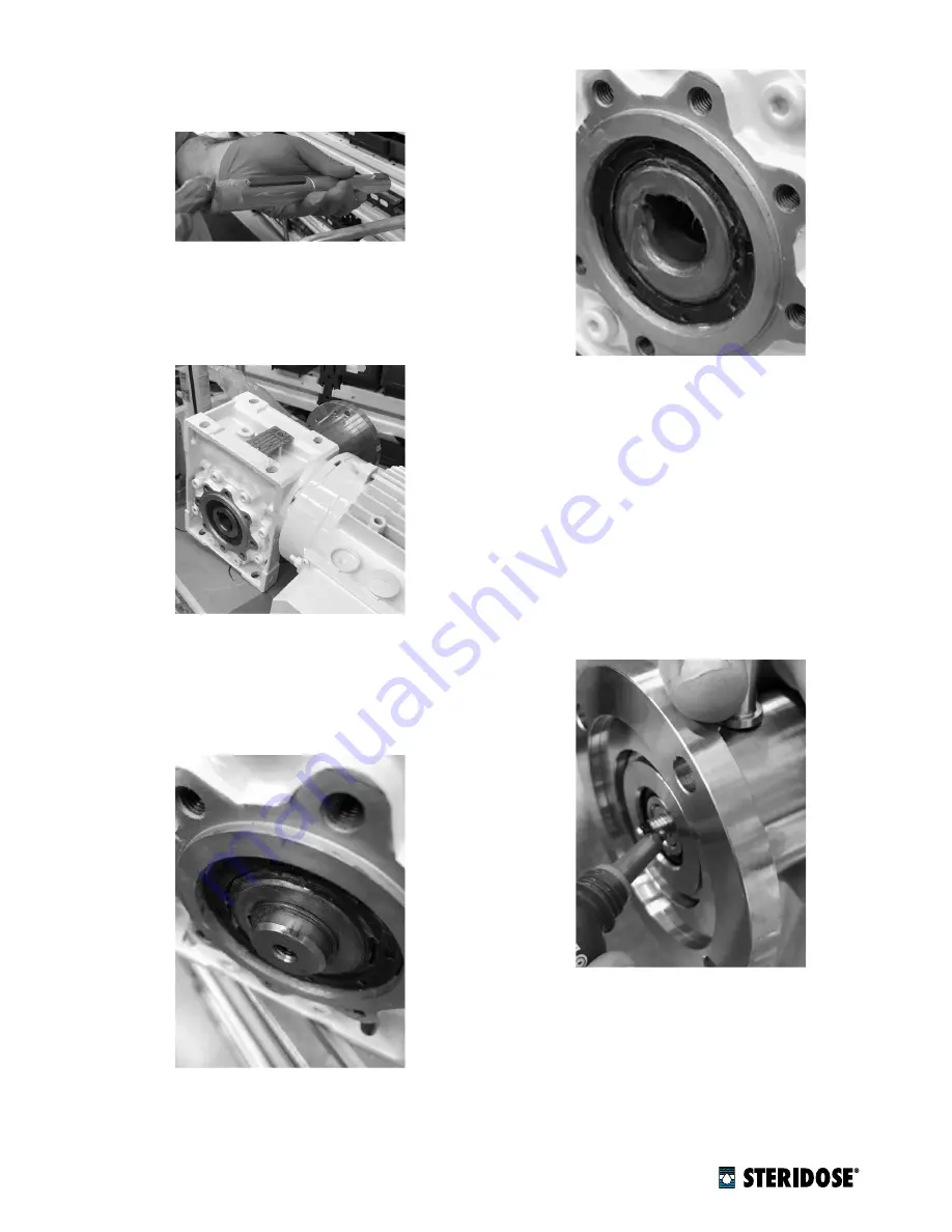
10. Put the drive unit on a flat surface. Verify that the

gearbox’s hollow shaft is completely free of deforma-
tions or burrs. A common file can be used for this

purpose.

11. Verify that the shaft can move smoothly up and down

the gearbox, all the way to the stop provided by the
bottom circlip. If necessary use a file to de-burr and
straighten the hollow-shaft keyway and/or the bot-
tom shaft key.

12. Once the shaft runs smoothly up and down the gear-

box, apply additional grease to the gearbox’s hollow
shaft.

13. Apply a suitable thread-sealant/locking liquid (e.g.

Loctite 243, Loctite 2400) to the Magnet Lowering
Device screw.

14. Screw the Magnet Lowering Device mounting screw

into the bottom end of the shaft and tighten to 17 Nm

(150 in-lb) with assistance of the mounting tool.

6

|

© Steridose

www.steridose.com

Содержание sterimixer

Страница 1: ...anual for future reference 1 2 Safety terminology and symbols 1 2 1 Hazard levels and indications The following symbols are used to indicate hazard levels DANGER Indicates a hazardous situation which if not avoided will result in death or serious injury WARNING Indicates a hazardous situation which if not avoided could result in death or serious injury CAUTION Indicates a hazardous situation which...

Страница 2: ...ngers Pay attention to the risks of electric shock or arc flash hazards Always bear in mind the risk of pinching fingers electrical accidents and burn injuries 1 4 2 Safety equipment Use safety equipment according to the company and local regulations 1 4 3 Electrical connections Electrical connections must be made by certified electri cians in compliance with all international national state and l...

Страница 3: ...12837 210 112838 a includes extended drive unit flange extended shaft and lowering device b includes lowering device assumes re using shaft and flange n Table 1 Part numbers for upgrade kits Refer to sec tion 7 for details for the magnet rotor when in the lowered position the use of the Magnet Lowering Device requires the drive unit to be equipped with the cooling jacket extension Retrofit kits ar...

Страница 4: ...n Figure 2 Example of a sign for the correct use of the Magnet Lowering Device 4 Steridose www steridose com ...

Страница 5: ...gearbox 3 Remove the shaft from the gearbox s hollow shaft 4 Remove the magnet rotor from the shaft STRONG MAGNETIC FIELDS HAZARD The Sterimixer impeller and magnetic rotor include strong magnets with the associated risk of pinching fingers and permanently damaging magnetic cards e g credit cards if being close to these compo nents HAZARD FOR WEARERS OF CARDIAC PACE MAKER The Sterimixer impeller a...

Страница 6: ... stop provided by the bottom circlip If necessary use a file to de burr and straighten the hollow shaft keyway and or the bot tom shaft key 12 Once the shaft runs smoothly up and down the gear box apply additional grease to the gearbox s hollow shaft 13 Apply a suitable thread sealant locking liquid e g Loctite 243 Loctite 2400 to the Magnet Lowering Device screw 14 Screw the Magnet Lowering Devic...

Страница 7: ...t cards if being close to these compo nents HAZARD FOR WEARERS OF CARDIAC PACE MAKER The Sterimixer impeller and magnetic rotor include strong magnets thus personnel equipped with pacemaker shall not handle these components Fix the magnet rotor on the shaft with the magnet rotor screw 18 For final tightening of the magnet rotor and Magnet Lowering Device mounting screw put the drive unit on its si...

Страница 8: ...he sensor works as intended Since the magnetic sensing range might pick up interference from other moving parts in the Magnet Lowering Device the sensor bracket has a slotted hole to allow for adjustment of the sensor position to eliminate interference Sensor technical data can be obtained from the sensor supplier s product information 8 Steridose www steridose com ...

Страница 9: ...www steridose com Installation Operation 9 ...

Страница 10: ...ing Practices that mini mize risk for process interference Steridose partners with the best distributors and repre sentatives in the industry all over the world Together we become the perfect mix a premium product with global references combined with local presence for product and application support Steridose AB Himmelsbodavägen 7 SE 147 39 Tumba Sweden Phone 46 8 449 9900 info steridose com www ...

Отзывы: