


3
The Touch Probe was designed to work with a Stepcraft CNC running UCCNC software. The Touch Probe can be
used with other CNC systems and software but Stepcraft would not be able to support such installations.
The installation software that comes with the Touch Probe will install several macros and a new screen set for
UCCNC. Custom buttons will now appear on the UCCNC screen to manage various functions for the Touch
Probe.
Installing the Touch Probe to the Stepcraft CNC
Installation of the Touch Probe is done in two separate parts; installing the wire to the board and connecting the
Touch Probe to the Stepcraft Tool Holder. Total installation time should take no more than 10 minutes and the
only tool required is a 2mm Allen Wrench and a small flat head screwdriver.
INSTALLING THE WIRE TO THE STEPCRAFT CIRCUIT BOARD
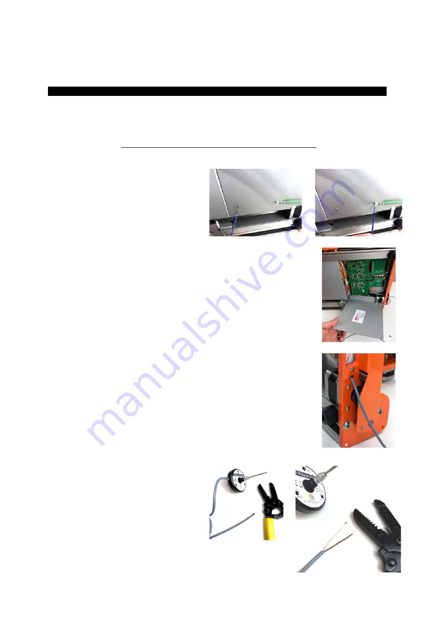
STEP 1
– Turn the machine on its side and
remove the two screws that secure the bottom
board cover using a 2mm Allen Wrench. One
screw should be securing the green ground wire
to the bottom of the machine.
STEP 2
– Remove the circuit board cover and set aside.
STEP 3
– Feed the Touch Probe cable through the hole in the rear of the Stepcraft CNC
machine into the circuit board area.
STEP 4
– Using a pair of wire strippers, remove
1” (25mm) of the outer gray cable sheath to
expose the white and brown wires inside.
Remove .25” (6mm) of the cable sheath of both
the white and brown wires. Using your fingers,
twist the bare copper wires so they do not fray,
which will make it easier to insert them into the
terminals in the next step.


