Assembly Instructions
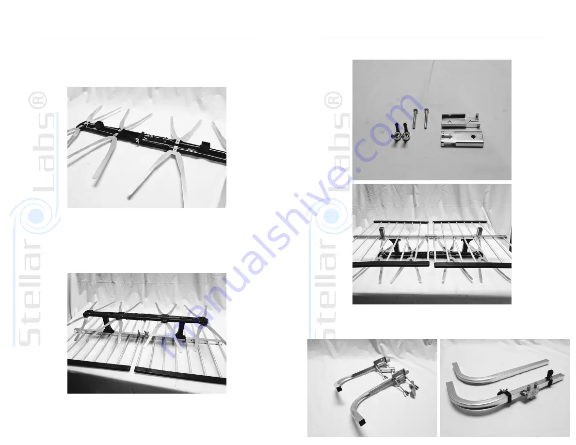
Figure D
Step 4: Unfold both array assemblies and tighten using wing nut located in the
center. (as shown in “Figure D”)
Figure E
Step 5: Attach array and reflector assemblies together using the stand-off connectors
on the reflector assemblies, and the corresponding mounting location on the array
assemblies. (as shown on “Figure E”)
Assembly Instructions
Step 6: Attach mounting brackets “B” (as pictured below) to the reflector assemblies
using the provided bolts and wing nuts. (as shown in “Figure “F”)
Figure F
Mounting Bracket B
Step 7: Attach mounting arms “A” to bracket “B” on one of the reflector assemblies
using provided bolts and wing nuts. (as shown in “Figure G”)
-Repeat this step for mounting arms “B” on the other reflector assembly.
(as shown in “Figure H”)
Mounting Arm A
Mounting Arm B


