background image

SAFETY INSTRUCTIONS 

additional safety instruction see EG-conformity declaration 


The vee-belt cover must be closed after each change of V-belt position by the hinge   


otherwise motor does not run  


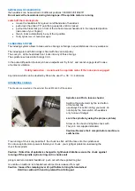
Before the machine is switched on


turn potentiometer down to “0” 


the selected speed must be checked against the maximum permissible workpiece diameter. 


For large, out-of-balance workpieces adjust lowest speed,  cut the workpiece before if possible 

octagonal with a bandsaw  


All clamping levers of spindle-/tailstock, tool rests etc must be tightened before beginning to work 


any operating pins /keys must be removed from chucks, indexing pin from spindle 


CLAMPING THE WORKPIECE 
 

Turning between centres with the 4-prong-mandrel and live centre


centre the workpiece at both ends outside the lathe (make bearings last longer)  

that markings are visible  (f.e. use centering device 05.0336.00 or 05.0337.00) 


press the driver prongs firmly into the workpiece by turning the hand wheel.  


for hardwood and exotics we recommend to make a boring with a drill D=4 mm 


tighten the set screws for the tailstock and the quill 


Overhung turning with chucks  
 
Cone-shaped chuck:

  Taper turn the workpiece to suit the chuck diameter and knock workpiece 

                                    outside of lathe into the chuck 
 

Face plate:


Secure the wooden discs with wooden screws (long enough) through the borings of plate 


Disc-chuck:


Screw the workpiece into the wooden screw: if necessary, drill core hole before 

                                    Wooden discs can be used to limit the depth of the woodworm-screw 
 

Jaw-chucks:


Increased risk to operator with jaws which project beyond the chuck body. 

                                    Remove the tightening key before starting the lathe 
 

div.chucks

                   i.e. SUPER NOVA2, NOVA G3, NOVA TITAN II, Sorby Patriot  

                                    see separate operating manual supplied with the chuck 


HANDWHEEL TAILSTOCK 

Please notice that the handwheel is no a precision part, , the run-out accuracy of the handwheel 
has 

NO influence to the run-out-accuracy of the spindle


TOOL REST 

Move the tool rest as close as possible to the workpiece, re-adjust it during the work.  
Take care of the square dimension  of your workpiece.  
Move tool rest just if workpiece is not turning. Clamp fastening screws. 


OUTRIGGER (Option) 

The outrigger can be placed at any position at the lathe bed 
 

Mounting 


Move tailstock and toolrest complete out to the righthandside of lathe bed 


Put the outrigger arm onto any position at the lathe bed and fix it 


Advise:  use headstock 180° degree swivelled and move it to the middle of lathe bed 

 The outrigger is placed at lefthand side of headstock 


Insert tool rest bottm part into the arm of the outrigger and clamp it 


Insert the supplied extension piece into the boring of the tool rest support, clamp it 


Insert the tool rest upper part into the extension piece 


Содержание KM 1450

Страница 1: ...th Potentiometer Changing the spindle direction Mainswitch ASS Safety System at Spindle Magnet Box with buttons and switches 5 0 Point adjustment for Tip to Tip alignment 6 Swivelling of Headstock 7 Operating the chucks Safety instructions clamping of workpieces 8 9 Tool Rest Base Support and upper part 10 Outrigger and Bed Extension options 10 Maintenance 11 Declaration of conformity ...

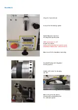
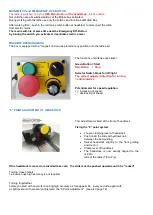
Страница 2: ...tton on off If button is pushed Lathe is disconnected from electric mains all buttons of Mobile Box without function Black Lock Pin for Headstock swivelling Vee Belt POulley with integrated indexing system Handle to lift motor for changing vee belt Black lock pin for 36 division indexing with automatically lock if in unlocked postion ...

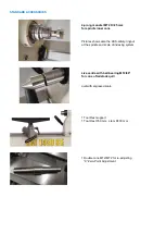
Страница 3: ...shows also the ASS safety ringnut at the spindle and scale of indexing system Live centre with ball bearing MT2 60 for cone of tailstock quill quill with engraved scale 1 Tool Rest support 1 Tool Rest 350 mm stem D 30 mm 1 Double cone MT2 MT2 for re adjusting 0 Zero Point Adjustment ...

Страница 4: ... chucks from spindle thread never insert the pin into the boring of the handwheel sleeve 1 long bar D 8 mm to push out the prong mandrel from spindle cone 1 Pin D 8 mm for chucks with a Bo 8 1 mm to loose the chuck from spindle thread ...

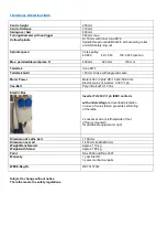
Страница 5: ... V 3 ph 2 HP 1 5 kW 50 60 Hz Electric mains of inverter 230 V 1 ph Vee Belt Poly V Belt J210 10 ribs Electric Box Inverter FU 230 V 1 ph EMV conform with undervoltage and overload protection In case of mains failure prevents self staring of the lathe 2 sockets at side of lefthandside of foot if foot is mounted for additional equipment or light Dimension of Lathe bed 1 150 mm Dimension over all 1 4...

Страница 6: ...e it near the lathe protect it from chips dust Ensure that the inverter has enough ventilation and is prevented against overheating STANDMODEL legs option If your lathe comes with dismounted legs Place the lathe onto a stable workbench or table screw on the legs from the lower side Adjust and level the lathe with spirit level by the M12 screws picture left shows parts supplied standard and rightha...

Страница 7: ...hile spindle is turning SPINDLE SPEED AND WORKPIECE DIAMETER The maximum permissible peripheral speed 3 000 U for a maximum workpiece diameter of 130 mm Watch the stickers at headstock for the adjusted speed and the max workpiece diameter The adjusted speed can be read out at the digital display CHANGING TURNING DIRECTION ROTATION OF SPINDLE With the potentiometer at mobile box righthanded rotatio...

Страница 8: ...black for left right The correct adjusted direction for turning anticlockwise Potentiometer for speed regulation increasing of speed _ decreasing of speed 0 POINT ADJUSTMENT OF HEADSTOCK This adjustment is fixed at the front of headstock Fixing the 0 point system Loosen clamping lever at headstock Push down the slide with yellow knob between the bed guiding Swivel headstock slightly to the front g...

Страница 9: ...h on spindle motor if the index pin is engaged Any division which can be devided by 36 can be used f e 36 9 4 divisions OPERATING CHUCKS The chucks are mounted at the external thread M 33x3 5 of the spindle Spindle Lock Pin to loosen chucks Switch off spindle motor by the red button of the mobile box use always this button during your work do not stop by the main switch at headstock only in case o...

Страница 10: ...e the wooden discs with wooden screws long enough through the borings of plate Disc chuck Screw the workpiece into the wooden screw if necessary drill core hole before Wooden discs can be used to limit the depth of the woodworm screw Jaw chucks Increased risk to operator with jaws which project beyond the chuck body Remove the tightening key before starting the lathe div chucks i e SUPER NOVA2 NOV...

Страница 11: ... screws and tighten all 4 screws MAINTENANCE The machine requires no maintenance The ball bearings are closed off dust proof and must not be lubricated Bright parts should be oiled occasionally to prevent corrosion We recommend Ballistol Universal Oil Item Nr 85 0200 20 If turning whet wood clean immediately the blank parts and oil them Movable parts i r excenter shaft of tool rest base quill with...

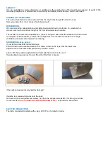
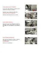
Страница 12: ...usting screws metal and rubber plates Double cone MT2 MT2 Insert Double cone into tailstock quill Loosen tailstock clamping Move tailstock close to the headstock until the cone is inserted into the spindle cone Clamp tailstock bevore the 0 Point Locking is re adjusted the yellow bolt slide must be pulled upwards until it is engaged locked ...

Страница 13: ...stock headstock and tailstock stands to each other Loosen tailstock clamping insert the long bar from lefthandside through the handwheel into the hollow spindle and push out the double cone with tailstock to the righthand side Fasten Tailstock and Quill lever insert long bar through the boring of tailstock handwheel and push out the couble cone to the lefthandside Hold cone to avoid fall down ...

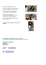
Страница 14: ...he inner front of lathe cheek without any light gap sight press on the bolt and fasten evenly the both black screws again check lift of stroke up down from the yellow bolt slide ACCESSORIES ATTACHMENTS and COPYING UNITS All recommended and available accessories see special accessory leaflet Drechselzentrum Erzgebirge Heuweg 4 09526 Olbernhau Deutschland Tel Phone 49 0 37360 6693 0 Fax Fax 49 0 373...

Страница 15: ...achinery directive 2060 42 EC Elektrische und elektronische Komponenten entsprechen den Anforderungen der Niederspannungsrichtlinie 2006 95 EC und der EMV Richtlinie 2004 108 EG Electrical control and its Components are in accordance with the Low Voltage 2006 95 EC and EMC 2004 108 EC Directives Angewandte harmonisierte Normen Harmonized standards applied EN ISO 12100 EN ISO 3746 EN ISO 13857 EN I...

Отзывы: