5
STEINDORFF
®
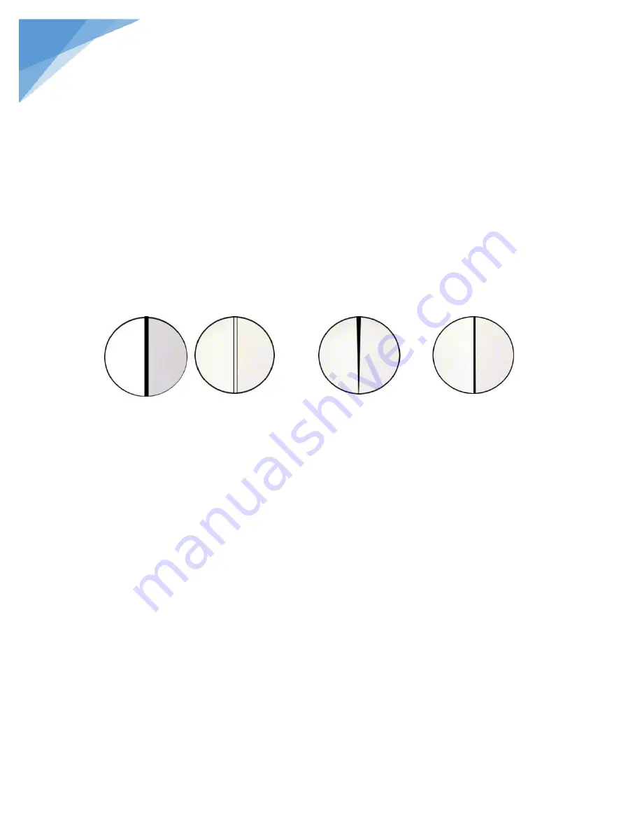
dust cover, insert the screw driver that goes along with the machine into the groove within the
bridge body and carefully regulate the line by watching through the eyepiece and turning the driver
slightly until it shapes as is shown in Picture 4. If it is like the line in Picture 3, adjust the left
screw. Turning the separation line knob (6) can move the comparison line continuously to have a
single, cutting or overlapping view field. When in the mode of overlapping view field, different
color filters applied to the right and left filter base will improve the result.
5. Choice and Adjustment of Magnification: The right and left objectives in use must have
the same magnification. Turning the magnification handle (9) changes their magnification power.
If the user wishes to have a bigger view field, just fit 0.3X objectives into the interfaces under the
objective group and re-adjust.
In order to put the right and left objectives in strictly the same magnification, the user must
adjust the magnification as follows:
Put the magnification reticles (36) on the right and left stage plates (20). Look through the
eyepiece at the scales images and focus until the two images are equally clear. Move the reticles
and make the reticle scales match with each other. If the right and left magnification is different,
Picture 2
The black and white lines
are too thick.
Picture 3
The black line shows
different widths at
both ends.
Picture 4
The line is a thin
straight black line.


