background image

Steelcase, Inc.

Grand Rapids, MI 49501
U.S.A.
1-888-783-3522

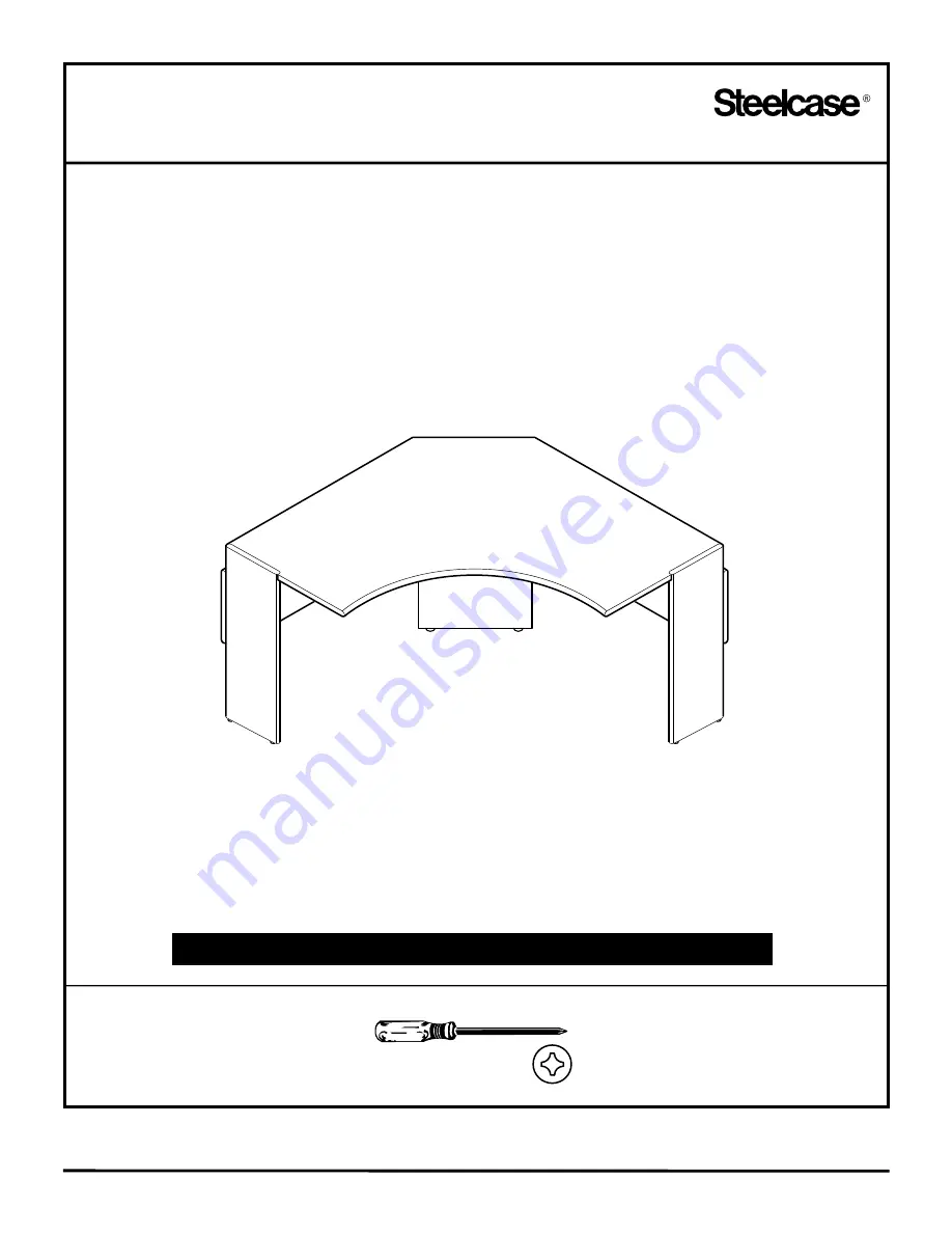
Radius Computer Table

Models:

8824RCT

8836RCT

8830RCT

NOTE:  Care should be taken to avoid scratching or marring painted surfaces!

Tools

Assembly Directions

Printed In U.S.A.

REV

93-9501353   A 

Page 1 of 7

#2 and #3 Phillips 

Содержание 8824RCT

Страница 1: ... U S A 1 888 783 3522 Radius Computer Table Models 8824RCT 8836RCT 8830RCT NOTE Care should be taken to avoid scratching or marring painted surfaces Tools Assembly Directions Printed In U S A REV 93 9501353 A Page 1 of 7 2 and 3 Phillips ...

Страница 2: ...ced tight against each other without gaps prior to tightening screws 1 NO SPACE SHOULD APPEAR AFTER ASSEMBLY 10 X 7 8 WOOD SCREW 4 EACH SIDE Position center wire tray between left and right hand back panel assemblies Secure center wire tray to center back panel assembly with 4 screws Secure center wire tray to each back panel assembly with 1 sheet metal screw on each side 2 10 X 7 8 WOOD SCREW 10 ...

Страница 3: ...d at 3 different heights 26 28 and 30 high Locate the set of holes for your heights Secure bracket back panel attachment to center back assembly with 3 machine screws NOTE Start all machine screws with fingers and continue tightening with power driver thus spreading flanges on brass inserts located in center back panel 3 26 HIGH WORKSURFACE 28 HIGH WORKSURFACE 30 HIGH WORKSURFACE 1 4 20 X 1 2 MACH...

Страница 4: ...tening with power driver thus spreading flanges on brass inserts located in end panel assembly When worksurfaces are assembled at 26 or 28 heights it would ease assembly if a spacer not included was placed under worksurface thus elevating bracket attaching holes with holes in end panel assembly NOTE It may be necessary to loosen screws and adjust brackets on underside of worksurface for proper fit...

Страница 5: ...nel assemblies with 3 machine screws each NOTE Start all machine screws with fingers and continue tightening with power driver thus spreading flanges on brass inserts located in each end panel assembly Secure bracket back panel attachment to worksurface with 3 wood screws 5 10 X 7 8 WOOD SCREW 3 REQUIRED 1 4 20 X 1 2 MACHINE SCREW 3 PER END ...

Страница 6: ...machine screw NOTE Start all machine screws with fingers and continue tightening with power driver thus spreading flanges on brass inserts located in center back panel Align holes in modesty panel with pre drilled holes in bottom of worksurface and secure with 4 wood screws each panel 6 10 X 7 8 WOOD SCREW 4 REQUIRED EACH PANEL 1 4 20 X 1 2 MACHINE SCREW ...

Страница 7: ... the manner shown below Secure center modesty panel to right and left hand modesty panels with 2 sheet metal screws Align 2 holes in center modesty panel flange with 2 pre drilled holes in underside of worksurface and secure with 2 wood screws NOTE Make sure all screws are tight carefully turn unit upright and adjust glides 7 10 X 7 8 WOOD SCREW 10 X 3 8 SHEET METAL SCREW ...

Отзывы: