


of adequate current capacity is usually
required.
Caution!
For electrical release of brake, apply
full rated coil voltage instantly. Do not increase
voltage slowly.
IV. General Maintenance - All Models
Warning!
Any mechanism or load held in
position by the brake should be secured to
prevent possible injury to personnel or damage
to equipment before any disassembly of the
brake is attempted or the manual release knob
or lever is operated on the brake. Observe all
cautions listed at the beginning of this manual.
Note 1
: Replacement part kits for many items
are available and contain retrofit instructions.
Note 2
: The 87,400 Maritime Series and
87,600 Navy Brakes as well as the 87,000
Marine Duty Brakes, though similar in
construction to the standard 87,000 Series
commercial brakes, utilize special materials
such as brass, bronze, ductile iron, etc. To
obtain correct replacement parts for the Series
87,000 Marine Duty or the Series 87,400 and
87,600 Brakes, obtain brake serial number and
consult factory.
A. Coil replacement - all models
All standard NEMA AC voltage coils are
available in kits. Select coil kit from appropriate
replacement parts list for the particular brake
series being serviced.
All standard NEMA DC voltage coils are
available in assemblies and may also be
obtained from appropriate parts list.
B. Friction disc replacement - all models
Note
: Replace friction disc in single disc brakes
when wear surface area is one-half the original
disc thickness. In multiple disc brakes, replace
all friction discs when throat of lever arm (17) is
within 1/16” of touching teeth of pinion (32).
1. Observe cautions and warnings preceding
Installation Procedure
, in Section I, Follow
Step A, then disconnect solenoid lead wires.
2. Continue with Steps B through D and Steps
G through J. Be sure to reconnect coil leads
before replacing housing (J).
C. Self-adjust maintenance
(See Figure 6)
Since the self-adjust brake automatically
adjusts itself for friction disc wear, mainte-
nance is held to a minimum. The solenoid is
factory set with a 13/16” to 15/16” air gap, and
requires no resetting, even when changing
friction discs.
Measure air gap with brake fully assembled
without housing.
Note
: To measure solenoid air gap on vertically
mounted brakes, grasp solenoid link to hold
plunger in a free horizontal position and move
toward solenoid frame until spring pressure
is felt. Holding firmly in this position, measure
air gap between mating (ground) surface on
solenoid frame and solenoid plunger. Adjust
to proper gap and check gap by again holding
plunger as directed.
The gap is determined by the position of wrap
spring stop (76). The normal operating gap is
13/16” to 15/16”. Should this change, follow the
steps listed:
1. If (stop) screws (76S) had been loosened
and retightened, the air gap may require
resetting. The gap is measured between
mating surfaces of plunger (2) and solenoid
frame (79), and may be increased by raising
slightly, or decreased by lowering slightly,
wrap spring stop (76). Be sure to retighten
(stop) screws (76S). Manually lift plunger
to maximum travel and release. Depress
plunger, manually or electrically, and allow
it to snap up. Repeat several times, then
recheck air gap. (For vertically mounted
brakes refer to Note in Section IV under Item
C).
2. Tang of wrap spring (71) must be below, and
must make contact with, wrap spring stop
(76) when solenoid lever (28) is manually
raised. If stop is bent outward, allowing
tang to bypass it, rebend to square position,
assemble correctly, and reset solenoid air
gap as described in Paragraph 1.
3. Should air gap disappear due to
overheating, oil or other lubricant may
have been applied to solenoid lever and
pinion assembly (8). Remove support plate
assembly (142). Loosen pressure spring
nut (19) until pressure spring (11) is free.
Remove cotter pin (8P) from solenoid lever
(28) and retaining ring (131R) from pivot
pin (131). Note location of spacer washer
(138) if used, and push pivot pin out to free
affected assembly. Remove retaining ring
(32R) from pinion (32) and disassemble.
Parts should be thoroughly cleaned in
M.E.K. or equivalent
solvent that does not
leave a film. Dry all
parts thoroughly and
reassemble. Rotate
pinion and wrap spring
clockwise until tang (A)
is aligned with centerline
of the upper hole of
the lever arm. Refer to
Figure 7. Reassemble
in reverse order. Do
not retighten cap screw
(19) until support plate
assembly is mounted on endplate. Refer to
Steps H and I of
Installation Procedure
to
complete assembly.
4. Check condition and positioning of pinion
(32) and rack (part of lever arm assembly,
17). Replace parts as necessary with com-
plete assemblies. See following Sections.
D. Solenoid lever and pinion assembly
replacement - all models except
Series 87,600
If pinion (32) teeth are worn, replace entire
assembly (8). Consult appropriate parts list for
kit number. Check sector gear of lever arm (17)
for wear.
E. Lever arm replacement - Series 87,000;
87,100 and 87,200 only
If sector gear teeth of lever arm (17) are worn,
replace entire lever arm assembly available
as a kit from appropriate repair parts list. Also
check pinion (32) teeth for wear. See Item
8. Do not attempt to use this aluminum lever
arm with Series 87,400 (Maritime) and Series
87,600 (Navy) Brakes.
F. Pressure spring stud and nut
replacement - Series 87,000; 87,100; 87,200
and 87,400
On older designs of above brakes, Item (152)
was threaded shoulder stud, Item (152P) was
a solid pin. These items have been replaced
by a spring tube, cap screw and spring pin.
Replacement of any individual component
requires replacement of all three older style
components. Consult appropriate repair parts
list for complete retrofit kit. The 87,600 (Navy)
Brake uses the pressure spring stud and nut
arrangement. Consult appropriate master plan
drawing for piece part numbers.
V. Troubleshooting
A. If brake does not stop properly or
overheats, check the following:
1. Is manual release engaged, and is motor
energized?
2. Friction discs may be excessively worn,
charred or broken.
3. Hub may have become loose and shifted
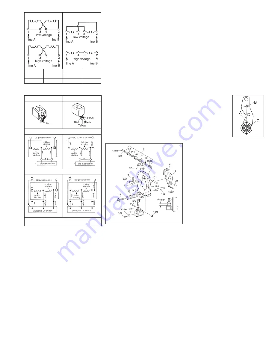
Figure 4
3 and 4
2
1
High voltage
–
2 and 4
1 and 3
Low voltage
Tie Leads
Power Line B
Power Line A
For
Class H Coil (colored)
Class B Coil (black)
DC Voltage Coil Connection
Figure 5
*Arc suppression used for coil above 48 Vdc.
**Follow polarity for switch to operate.
Electronic Switch**
(New Style)
Mechanical Switch
(Old Style)
Class B
Class H
Figure 6
Figure 7


