background image

®

Note: neutral wire required

06/11

Pub. No. 572-C

- 6 -

Instructions for Installation and Use

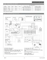
Table 3 - Wire and Fuse sizes (S170-3)

Model

SMS-80R-3

SMS-100-3

SMS-125-3

SMS-145-3

Watts

8,000

9,800

12,300

14,400

Amps

22.2

27.3

34.1

40.0

Voltage

208

208

208

208

Phase

3

3

3

3

Breaker to Power Unit

1@30A - #10 AWG copper 90°C

1@35A - #8 AWG Copper 90°C

1@50A - #6 AWG Copper 90°C

1@50A - #6 AWG Copper 90°C

Power Unit to Heater

#10 AWG copper 90°C

#8 AWG Copper 90°C

#6 AWG Copper 90°C

#6 AWG Copper 90°C

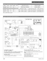
Figure 7 - Electrical Connections (S170-3)

S170-3 (208V / 3PH power unit)
Instructions for Installation

The power unit of the S170-3 is controlled by the digital control.

 Control panel is connected to power unit via data cable.

 Only one control panel can be connected to the power unit.

Temperature Sensor:

 Temperature Sensor is needed to operate S170-3. See section 

3.3 for correct temperature sensor placement.

Two relay outputs (120V / 1PH)

 For driving a fan (max. 100W) and lighting (max. 100W).

Fuses on the electronics card (if a fuse has blown, see section 
3.2.2):

 40mA fuse for electronic unit.

 Two 2.5 Ah fuses for relay outputs U1, U2, A1, A2.

Technical Specifications:

 Max. heater power rating: 14.4kW

 Max. length of data cable: 25 m 

Wire Size AWG 90°C

Heater

max. 14.4 kW

G7Z

Power supply

208V / 3PH

max. 14.4 kW

N

L1

L2

L3

N

L

N

L

120V / 1PH

max. 100 W

Slow type

Ceramic

Slow Type

40 mA

T2.5 Ah 

A1

A2

L1

N

L2

L3

L1

L2

L3

L1 L2

 U1 U2 A1 A2

N

N

A1

A2

L1

L2

L3

GND

GND

GND

GND

GND

Temperature sensor

Data cable

Control panel

Factory wiring

Installation wiring

Lighting (optional)

Fan (optional)

Fuse for 

electronic card

Fuse for 

relay outputs

Main switch

Blue/Bleu

Yellow/Jaune

White/Blanc

Red/Rouge

120V / 1PH

max. 100 W

Low voltage wiring only
(data and sensor cable)

Minimum 18awg, copper

, 90ºC wire for 

A1 and 

A2 wires

Содержание S170-1

Страница 1: ... Instructions For Installation 3 1 Installing the Control Panel 3 2 Installing the Power Unit 3 2 1 Electrical Connections 3 2 2 Resetting the Overheat Protector 4 Spare parts Steamist Limited Warranty 1 1 General The Steamist Digital Sauna Control unit can be used to control sauna heaters within an output range of 2 3 15 kW The control unit consists of a control panel a power unit and a sensor Se...

Страница 2: ...st be done by professional maintenance personnel No user serviceable parts inside 2 1 Using the Heater WARNING Before switching the heater on always check that there isn t anything on top of the heater or inside the given safety distance Start the heater by pressing the I O button on the control panel When the heater starts the top row of the display will show the set temperature and the bottom ro...

Страница 3: ... next time Set the delay time heater off Press the button to set the ON time to maximum 1 00 hr Press the button again to enter the delay time mode The temperature indicator light switches off Delay time symbol blinks on the screen Select the desired delay time using and butttons The adjustment is made in 10 minute increments Press and hold the button to make the time change faster The adjustment ...

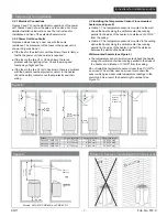
Страница 4: ... an ambient temperature of above 32 F 0 C where is can be accessed conveniently See Figure 4 3 2 Installing the Power Unit Install the power unit to a wall outside the sauna room in a dry place with an ambient temperature of above 32 F 0 C See Figure 5 for instructions on how to open the power unit cover and how to fix the unit to the wall NOTE Do not embed the control unit into the wall since thi...

Страница 5: ... type Fuse for electronic card Ceramic Slow Type Fuse for relay outputs 40 mA T2 5 Ah A1 A2 L1 L2 L1 L2 L1 L2 U1 U2 A1 A2 N N A1 A2 L1 L2 L1 L2 GND A1 A2 L1 L2 GND GND GND GND GND Factory wiring Installation wiring Main switch Wall mounted heater max 9 kW GND Low voltage wiring only data and sensor cable Temperature Sensor Data Cable S170 1 240V 1PH power unit Instructions for Installation The pow...

Страница 6: ...erature Sensor is needed to operate S170 3 See section 3 3 for correct temperature sensor placement Two relay outputs 120V 1PH For driving a fan max 100W and lighting max 100W Fuses on the electronics card if a fuse has blown see section 3 2 2 40mA fuse for electronic unit Two 2 5 Ah fuses for relay outputs U1 U2 A1 A2 Technical Specifications Max heater power rating 14 4kW Max length of data cabl...

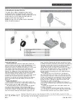
Страница 7: ...in the power unit and service is required If the fuse in the line U1 or U2 has blown there is a problem with the lighting or fan Check the wiring and functioning of light and fan If the fuse in the line A1 or A2 has blown there is a problem with the heater s overheat protector circuit In the heater check the safety contactor overheat protector and their wiring 3 3 Installing the Temperature Sensor...

Страница 8: ...e period of one year from the original purchase date This limited warranty covers faults in manufacture and material only and includes the exchange of new parts supplied by the manufacturer or the manufacturer s agent after the defective parts are returned to Steamist The replacement of parts under warranty does not extend the warranty period beyond the original one year period In addition Steamis...

Отзывы: