D2534-01-04
4.2~ELECTRICAL (continued)
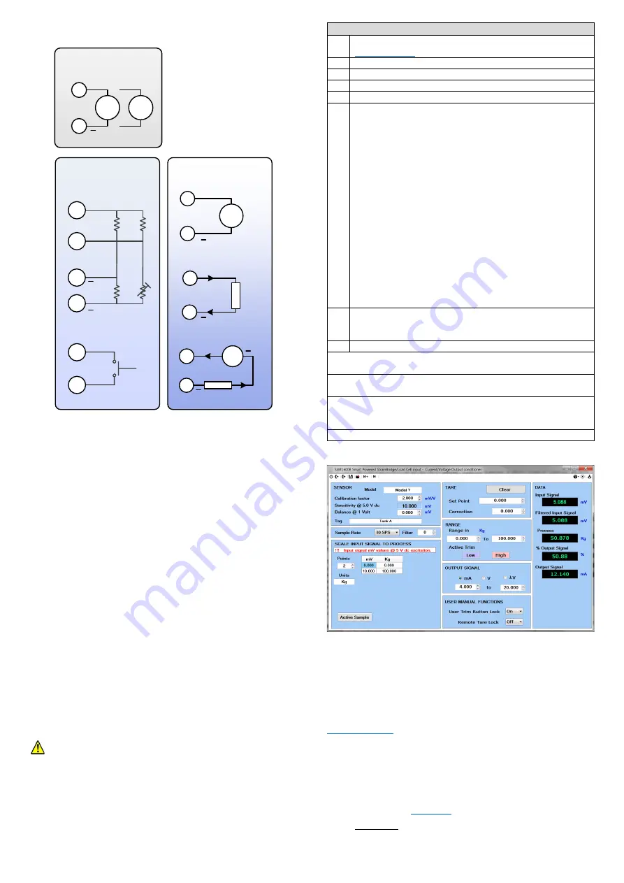
SEM1600B Connections
1
+
SUPPLY
2
Vdc
Vac
INPUT
4
Voltage
5
3
6
mA
6
5
mA Externally Powered
OUTPUT
Vs
Tare
Vexc
Bridge Input
Vexc
8
7
10
11
9
12
V
out
+
+
+ +
+
+
5~FEATURES
.
5.1~STATE LED
The
State LED is GREEN under normal run conditions indicating an
in-range input signal. If the input signal is out of range or is lost, the
State LED will light RED.
5.2~TARE
If PINs 9 and 12 are shorted (momentarily) the input value will be
overwritten by the TARE setpoint value (normally zero).
5.3~ACTIVE TRIM
Down Adjust button press: Configures the low scale output against the
live input signal.
Up Adjust button press: Configures the high scale output against the
live input signal.
Press and keep button pressed - the state light will go off for a few
seconds then flash at a fast rate before returning to a steady state.
Release button. Adjust operation complete. Output adjusts to levels
pre-set in the software configuration.
6~USER CONFIGURATION.
The SEM1600B can be configured using a Windows PC.
Live input and output values can also be viewed on a PC or a suitable
Android device.
6.1~PC CONFIGURATION USBSpeedLink Software
During
configuration the equipment takes its power from the
USB port, therefore no power connection is required. The equipment
can be configured whilst powered but the computer used must be
portable battery-powered or a USB isolator should be used to isolate
the SEM1600B from the supply earth to avoid grounded earth loop
effects.
Observe any warning information given in the software.
PC Configuration steps
1
Download and install the USBSpeedLink software from
2
Run the software and open to the correct screen for the SEM1600B
3
Connect to the PC using an A to Mini B USB lead.
*1
4
Read the SEM1600B configuration into the software.
5
Configure the device to the required settings for operation.
5.1
SEM1600B configuration options:
Model:
Free type field
Calibration factor
: From sensors/Load cell datasheet.
Balance:
From Load cell calibration certificate if available.
Tag:
Free type field
Sample rate:
Samples per second
Filter
: Rate in seconds
Scale points:
2 up to 6 points
mV to Process value table:
mV input to process table
Units:
Free type field for Engineering unit
Tare Clear:
Removes Tare
Tare Setpoint:
Value the input is set to on Tare action
Tare Offset:
Difference between input and Tare setpoint on
tare action
Output Signal:
mA, V,
±V
Output Range:
Any within limits
Button locks:
On, Off
6
Read Data:
Live data can be displayed showing input and output
values. This can only be done if the device is powered as well as
connected to the software via the USB lead.
*3
7
Write/Save:
the configuration to the device.
*2
*1
Once only, on the first time connecting to the SEM1600B, drivers will
install to the PC, allow time for this before proceeding.
*2
The configuration is not saved onto the device unless the configuration
screen is sent.
*3
The SEM1600B can be configured whilst connected and powered, but a
portable battery powered computer or USB isolator must be used to avoid
the effects of ground loops.
.
Configuration screen
6.2~ANDROID MONITORING USBView Software
Using
a suitable OTG USB lead to connect the SEM1600B to an
Android device, live data reading can be taken.
The USBView app. can display input temperature/value, output mA/V
and the Tag information.
USB Software can be downloaded free of charge from
www.status.co.uk
This guide is also available online at
Status Instruments Ltd, Status Business Park, Gannaway Lane, Tewkesbury, Gloucestershire, UK, GL20 8FD,
Web Page: www.status.co.uk,
Email: [email protected]
Technical Support: [email protected]
Tel: +44 (0) 1684 296818, Fax: +44 (0) 1684 293746


