background image

12

electrIcal data

General

Check  the  boiler  model  and  rating  plate  information  against  the 

characteristics of the branch circuit electrical supply. Do not connect 

the boiler to an improper source of electricity.  

Voltage applied to the boiler  should not vary more than + 5% to -10% 

of the model and rating plate marking for satisfactory operation.

Do not energize the branch circuit for any reason before the boiler is 

filled with water. Doing so may cause the heating elements to burn 

out. Such damage is not covered under the terms of the warranty.

The  branch  circuit  is  connected  to  the  block  through  an  opening 

provided on top of the boiler.

The  boiler  should  be  connected  to  a  separate,  grounded,  branch 

circuit with overcurrent protection and disconnect switch. These are 

part  of  the  electrical  supply  system  not  components  of  the  boiler, 

as such they are obtained locally. The boiler should be grounded in 

accordance with national and local codes.

Branch cIrcuIt

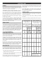
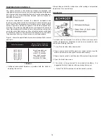
The branch circuit wire size should be established through reference 

to the National Electrical Code or other locally approved source in 

conjunction with boiler amperage rating. Branch circuit wiring which 

connects  to  the  boiler  terminal  block  should  be  temperature  rated 

at 75°C. For convenience, portions of the wire size tables from the 

Code are reproduced here. It is suggested the electrician size the 

branch circuit at 125 percent of the boiler rating and further increase 

wire size as necessary to compensate for voltage drop in long runs. 

Branch circuit voltage drop should not exceed 3% at the boiler.

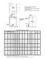
calculatInG aMperaGe/ 

oVercurrent protectIon

The boiler is factory wired for connection to three wire single-phase 

or  three  and  four  wire  three-phase  branch  circuits.  In  addition,  a 

ground conductor may be required.

A diagram of the wiring “as built” is furnished with the boiler for the 

electrician’s use. An amperage table is on pages 7 & 12 of this manual. 

The boiler model and rating plate provides full load amperage data. 

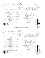
Typical or Standard wiring diagrams are provided on pages 13 & 14 

of this manual.

The rating of the overcurrent protection should be computed on the 

basis of 125 percent of the total connected load amperage.   Where the 

standard ratings and settings do not correspond with this computation, 

the next higher standard rating or setting should be selected.
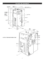
BoIler cIrcuIts

The  boiler’s  electrical  components  are  pictured  and  identified  on 

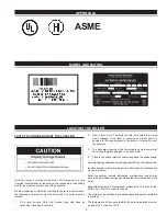
page 8. The model and rating plate illustration on page 9 identifies the 

electrical characteristics. Basically, there are two electrical circuits:

•  The  control  circuit,  where  the  temperature  control  directly  or 

indirectly operates the contactor coils.

•  The power circuit, which is operated by the control circuit, carries 

the electrical load of the heating elements.

The following describes the circuits and includes typical wiring diagrams. 

All circuits are designed for 60 or 50 Hertz alternating current.

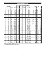
Refer to ELECTRICAL CONFIGURATION TABLE, below, and wiring 

diagram provided with your boiler before completing connections to 

electrical supply.

NOTE:  Wiring  diagrams  in  this  manual  are  typical  examples.  The 

specific wiring diagram “as built” for your boiler is typically attached to 

the “inner side” of the control panel. 

control cIrcuIt

All control circuits are operated on single-phase 120V. A transformer 

is used in the control circuit. 

Control  circuit  wiring  is  14 Awg,  THHN  or  THWN  type,  rated  600 

volts, 105°C.

Seperate instructional literature is provided with the boiler for step control.

portion of table 310-16

Allowable Ampacities of Insulated 

Copper Conductors

Not more than three conductors in 

raceway or cable or direct burial 

(based on ambient temperature of 

30°C, 86°F.)

portion of table 310-16

Allowable Ampacities of Insulated 

Aluminum and Copper-Clad 

Aluminum Conductors

Not more than three conductors in 

raceway or cable or direct burial 

(based on ambient temperature of 

30°C, 86°F.)

size

temperature 

rating of 

conductor. see 

table 310-13 in 

code

size

temperature 

rating of 

conductor. see 

table 310-13 in 

code

awG

McM

75°c (167°f) 

types rh, 

rhw, ruh (14-

2), thw, thwn, 

Xhhw, use

awG

McM

75°c (167°f) 

types rh, 

rhw, ruh (12-

2), thw, thwn, 

Xhhw, use

18

16

14

12

10

8

- - - - -

- - - - -

15

20

30

45

12

10

8

6

4

3

15

25

40

50

65

75

6

4

3

2

1

1/0

65

85

100

115

130

150

2

1

1/0

2/0

3/0

4/0

90

100

120

135

155

180

2/0

3/0

4/0

250

300

350

175

200

230

255

285

310

250

300

350

400

500

600

205

230

250

270

310

340

400

500

600

700

750

800

900

335

380

420

460

475

490

520

700

750

800

900

1000

1250

1500

375

385

395

425

445

485

520

1000

1250

1500

1750

2000

545

590

625

650

665

1750

2000

545

560

These capacites relate only to conductors 

described in Table 310-13 in Code.

For ambient temperatures over 30°C, see 

Correction Factors, Note 13 in Code

Содержание ASME SW 37-670

Страница 1: ...for future reference COMMERCIAL ELECTRIC BOILERS Thank you for buying this energy efficient boiler from us We appreciate your confidence in our products MODELS SW 37 670 INSTALLATION OPERATION SERVICE MAINTENANCE LIMITED WARRANTY A DIVISION OF A O SMITH CORPORATION RENTON WASHINGTON www statewaterheaters com ASME ...

Страница 2: ...t the type of hazard what can happen if you do not follow the safety message and how to avoid the risk of injury The California Safe Drinking Water and Toxic Enforcement Act requires the Governor of California to publish a list of substances known to the State of California to cause cancer birth defects or other reproductive harm and requires businesses to warn of potential exposure to such substa...

Страница 3: ...may also cause erratic control system operation on ELECTRONIC CONTROL models This boiler must be connected to a grounded metal permanent wiring system or an equipment grounding conductor must be run with the circuit conductors and connected to the equipment grounding terminal or lead on the boiler HYDROGEN GAS FLAMMABLE Hydrogen gas can be produced in a hot water system served by this boiler that ...

Страница 4: ...when standing in water When replacing fuses always use the correct size for the circuit See page 12 through 14 The principal components of the heater are identified on page 8 The model and rating plate on page 9 interprets certain markings into useful information Both of these references should be used to identify the heater its components and optional equipment 2 The installation must conform wit...

Страница 5: ... 4 4 4 3 3 3 3 1 1 1 1 SW SW SW SW SW 96 96 96 96 96 330K 390K 420K 450K 480K 36 36 36 36 36 38 38 38 38 38 16 16 16 16 16 69 1 2 69 1 2 69 1 2 69 1 2 69 1 2 17 17 17 17 17 1 1 2 1 1 2 1 1 2 1 1 2 1 1 2 17 17 17 17 17 22 22 22 22 22 5 5 5 5 5 4 4 4 4 4 1 1 4 1 1 4 1 1 4 1 1 4 1 1 4 SW SW SW SW 150 150 150 150 540K 600K 660K 720K 46 46 46 46 44 44 44 44 19 19 19 19 69 1 2 69 1 2 69 1 2 69 1 2 20 20...

Страница 6: ...0 1800K 1860K 1980K 2100K 66 66 66 66 56 56 56 56 28 28 28 28 90 1 2 90 1 2 90 1 2 90 1 2 25 1 2 25 1 2 25 1 2 25 1 2 2 1 2 2 1 2 2 1 2 2 1 2 30 30 30 30 33 33 33 33 7 3 4 7 3 4 7 3 4 7 3 4 8 8 8 8 2 2 2 2 SW SW SW SW 500 500 500 500 2200K 2340K 2460K 2580K 72 72 72 72 62 62 62 62 31 31 31 31 90 1 2 90 1 2 90 1 2 90 1 2 26 1 2 26 1 2 26 1 2 26 1 2 2 1 2 2 1 2 2 1 2 2 1 2 34 34 34 34 36 36 36 36 7 ...

Страница 7: ... 60 2 90 4 90 6 60 1501 1668 1299 1443 648 720 792 864 542 602 663 723 SW SW SW SW SW SW SW 220 220 220 220 220 220 220 780K 840K 900K 960K 1020K 1080K 1140K 2 662 140 2 866 920 3 071 700 3 276 480 3 481 260 3 636 040 3 890 820 3198 3444 3690 3936 4182 4428 4674 52 56 60 64 68 72 76 10 10 10 10 10 10 10 6 90 4 60 9 90 1 30 10 90 8 90 2 120 6 90 4 120 4 90 6 120 2 90 8 120 936 1008 1080 1152 1224 1...

Страница 8: ...8 FEATURES AND COMPONENTS ACTUAL CONFIGURATION MAY VARY ...

Страница 9: ...o the area adjacent to the boiler or to lower floors of the structure 3 The discharge opening of the temperature and pressure relief valve should always be piped to an open drain 4 Close to the point of major hot water usage and the power supply Hot water piping and branch circuit wiring should be as short as possible Insulate hot and cold water piping where heat loss and condensation may be a pro...

Страница 10: ...out being certain the boiler is filled with water and a properly sized pressure relief valve is installed in the relief valve opening provided The pressure rating of the relief valve should be equal to or less than the rated pressure capacity of any component in the system including the boiler Should the valve need to be replaced call the toll free phone number listed on the back of this manual fo...

Страница 11: ...ing increase in water pressure due to thermal expansion Thermal expansion can cause premature tank failure leakage This type of failure is not covered under the limited warranty Thermal expansion can also cause intermittent pressure relief valve operation water discharged from the valve due to excessive pressure build up This condition is not covered under the limited warranty The pressure relief ...

Страница 12: ...ith this computation the next higher standard rating or setting should be selected Boiler Circuits The boiler s electrical components are pictured and identified on page 8 The model and rating plate illustration on page 9 identifies the electrical characteristics Basically there are two electrical circuits The control circuit where the temperature control directly or indirectly operates the contac...

Страница 13: ...ITH THERMOSTAT NOTE S 1 IF A MANUAL RESET HLMT IS USED THE SECOND AUTO RESET HLMT SWITCH IS NOT USED STD WIRING OPTIONAL OR FIELD WIRING AS REQ D NOTE S 1 IF A MANUAL RESET HLMT IS USED THE SECOND AUTO RESET HLMT SWITCH IS NOT USED STD WIRING OPTIONAL OR FIELD WIRING AS REQ D CONTACTOR COIL INDICATION LIGHT ...

Страница 14: ...ION LIGHT 1 OFF ON 2200 2 OFF ON 135 3 OFF ON 4 20MA 4 OFF ON 0 10VDC 5 DS PROP 6 PROG UN 7 OFF VER 8 SEC MN 1 DELAY 1 2 DELAY 2 3 DELAY 3 4 1 5 2 6 4 7 5 8 16 THE ABOVE DIP SWITCH SETTINGS ARE AN EXAMPLE FOR THE FOLLOWING 2200 OHM PROPORTIONAL PROGRESSIVE VERNER OFF SECONDS 10 SECOND 3 STAGE INPUTS DELAY STAGES 1 OFF ON 2200 2 OFF ON 135 3 OFF ON 4 20MA 4 OFF ON 0 10VDC 5 DS PROP 6 PROG UN 7 OFF ...

Страница 15: ...ay be in the control circuit in addition to the automatic high limit previously described The control has an adjustable range of 110 F to 290 F and activates and locks on a temperature increase When the temperature declines the manual reset high limit can be reset A manual reset high limit is an optional substitution for one of the automatic high limits mentioned above The manual reset button is l...

Страница 16: ...pproximate time to burn relationship for normal adult skin Water Temperature Time to Produce 2nd 3rd Degree Burns on Adult Skin 180 F 82 C 160 F 82 C 150 F 82 C 140 F 82 C 130 F 82 C 120 F 82 C 80 F 82 C Nearly Instantaneous About 1 2 second About 1 1 2 seconds Less than 5 seconds About 30 seconds More than 5 minutes FIGURE 1 Additional instructional literature is provided with the boiler for adju...

Страница 17: ...idential pipe dope thread cutting oil solder flux dirt and other foreign materials breakdown to form gas This is indicated by a continuing need for purging even through the system is closed 2 Pump seal leakage Acidic water low pH and contamination such as soil and sand result in premature or recurring pump seal failures 3 Automatic air valve leakage Contaminants cause sticky sealing surfaces and r...

Страница 18: ... switch serving the boiler is in the ON position The pilot switch es on the cabinet front should be on In some installations the boiler electrical service may be limited by the power company or boiler controls If the boiler operates on a controlled circuit heat may be effected 2 Check the fuses The electrical disconnect switch usually contains fuses The boiler has fuses located behind the cabinet ...

Страница 19: ...tive charges for forwarding the new tank or replacement part from the nearest distributor and returning the claimed defective tank or part to such distributor c All cost necessary or incidental for any materials and or permits required for installation of the replacement tank or part 5 LIMITATION ON IMPLIED WARRANTIES Implied warranties including any warranty of merchantability imposed on the sale...

Страница 20: ...A DIVISION OF A O SMITH CORPORATION RENTON WASHINGTON Technical Support 800 527 1953 Parts Department 800 433 2515 www statewaterheaters com ...

Отзывы: