3
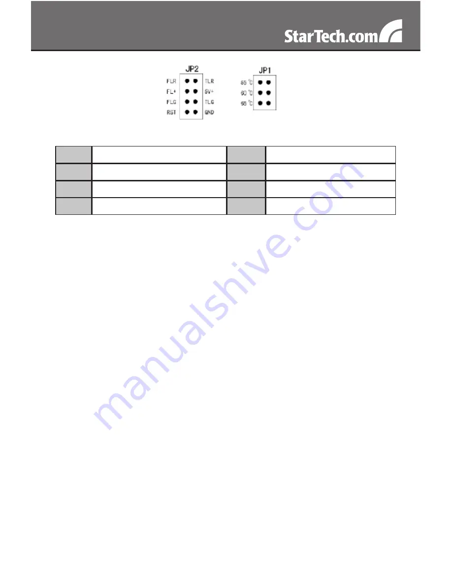
JP2
FLR
Fan Failure Detect (red)
TLR
Temperature Detect (red)
FL+
Fan Failure Detect (+)
5V+
5V power
FLG
Fan Failure Detect (green)
TLG
Temperature Detect (green)
RST
Reset switch
GND
Ground
Hardware Installation
Remove one of the drive trays by pressing on the left side of the
1.
drive tray. This will cause the tray’s locking arm to swing out. Hold the
arm and pull the tray out.
Place the hard drive into the tray. Line up the holes in the bottom of
2.
the tray with the holes in the bottom of your drive. Use the provided
screws to secure the hard drive to the tray.
Slide the tray back into the slot. When the tray is all the way back into
3.
the slot, press the locking arm back in until you hear a “click” sound.
This indicates that the tray and hard drive are properly installed.
Repeat these steps for the other hard drives.
4.
Install the backplane into open 5.25” drive bays in your system case.
5.
Follow the directions from the case manufacturer.
Use the 7-pin Serial ATA (SATA) signal cables to connect the 7-pin
6.
hard drive (HDD) ports on the back of the backplane to your SATA or
SAS controller.
NOTE:
Some SAS controller cards use an SFF-8484 or SFF-8087
connector. A special breakout cable to 7-pin SATA connectors would
be required to plug into the backplane
(ie. StarTech.com ID: SAS84SS450).


