


Introduction
Thank you for purchasing a StarTech.com 10/100 Mbps rackmount Ethernet switch. This
high performance switch provides you with 24 (ES3124R) or 32 (ES3132R) Fast Ethernet
ports to segment network traffic, extend connection distance, and convert data packets
between different transmission speeds. Using store-and-forward switching, auto-
negotiation, and auto-MDI/MDI-X technologies, these switches relieve bandwidth
bottlenecks and provide faster response times for your network.
Features
• Complies with IEEE 802.3 10BaseT Ethernet and 802.3u 100BaseTX Fast Ethernet
standards
• Supports 10BaseT/100BaseTX and Full Duplex/Half Duplex auto-negotiation on all
ports
• Uses advanced IEEE 802.3x-compliant flow control (Full Duplex) and backpressure
(Half Duplex) to reduce congestion and prevent packet loss
• Supports auto-MDI/MDI-X detection on all ports
• Supports store-and-forward switching architecture
• Designed for standard 19” rackmounts
• Backed by StarTech.com’s two-year warranty
Before You Begin
WARNING!
The Fast Ethernet switch must be installed and operated in an environment
with temperatures between 32-131ºF (0-55ºC) and humidity levels of 10-95% (non-
condensing)
. Make sure that the switch is kept away from heating sources and that the
vents at the side of the device are not blocked. Do not place any objects on top of the
device. Make sure that no water or moisture enters the unit. If necessary, use a
dehumidifier to reduce humidity near the device.
Requirements
The length of UTP cable between the switch and a connected device can not exceed 300ft
(100m)
. To reach 100 Mbps transfer speeds, your network cables will need to comply
with EIA/TIA 568 specifications and Category 5 (or higher) standards. StarTech.com
carries a wide range of networking cables to suit your needs. Visit www.startech.com
and click on the “Networking” tab for more product information.
2
Contents
This package should contain:
• 1 x Fast Ethernet switch
• 1 x power cord
• Rackmount accessories
Installation
1. Plug the power connector into the power socket on the back of the unit. Plug the
other end into an available power source. The green Power LED on the front of the
switch should now be lit.
2. Plug one end of your network cable into an open RJ-45 port on the switch and plug
the other end into your network device.
NOTE:
Since all ports on the device are auto-MDI/MDI-X ports, you can use straight-
through cables to connect to both workstations and other switches/hubs.
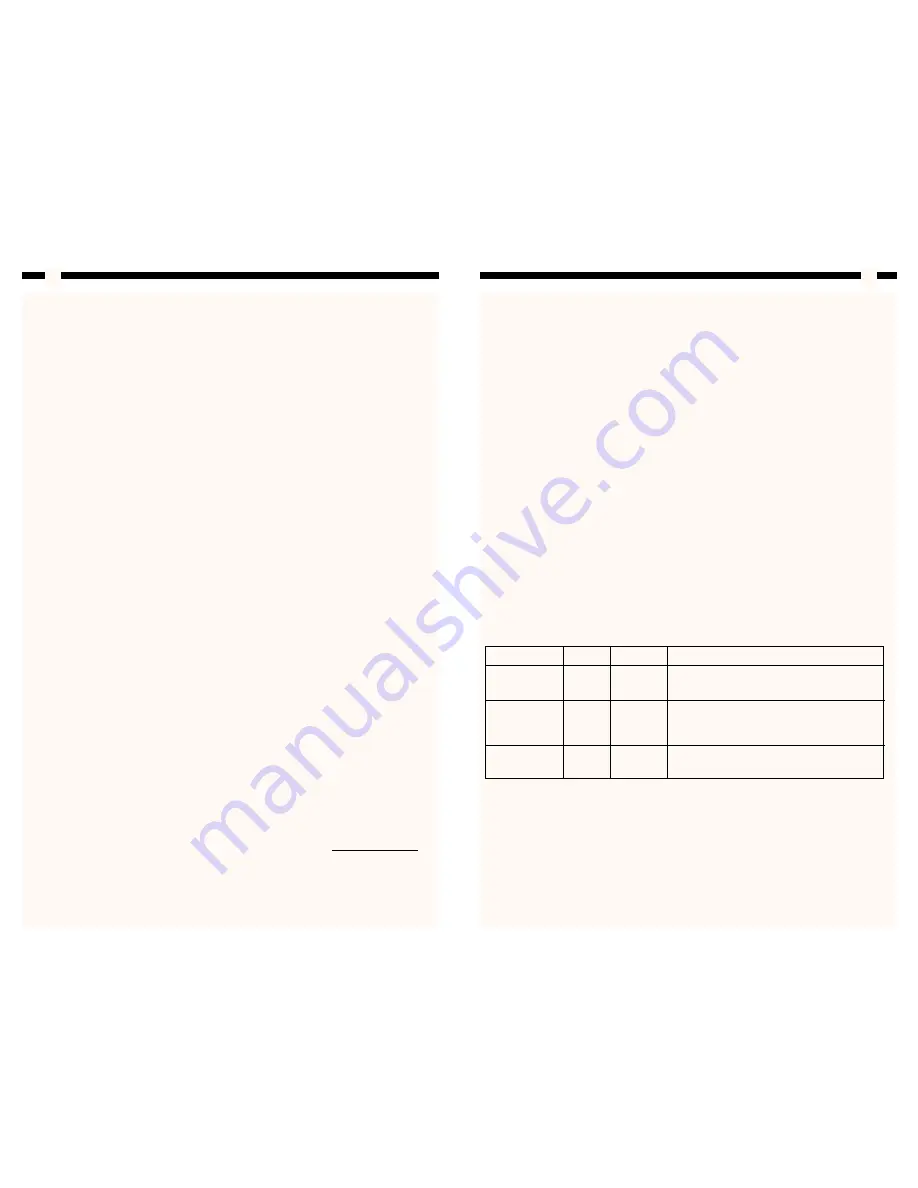
Monitoring Your Device
The LEDs on the front of the switch are your best indication of the switch’s activity.
There is one power LED per switch. There is one LNK/ACT LED and one 10/100M LED
per port.
3
LED
Color
Status
Description
PWR
Green
On
Power is supplied
(Power)
Off
No power
LNK/ACT
Green
On
Valid link established
(Link/Activity)
Flashing
Data packets received
Off
No link established
10/100M
Yellow
On
Port is running at 100Mbps
Off
Port is not connected or running at 10Mbps


