


Instruction Manual
4
Installation
1. The Network Switch is designed to sit on a flat surface (such as a desktop) or be
securely mounted to a wall or similar surface. If you wish to mount the Network
Switch, first prepare the surface by installing mounting screws (not included)
otherwise skip to Step 5.
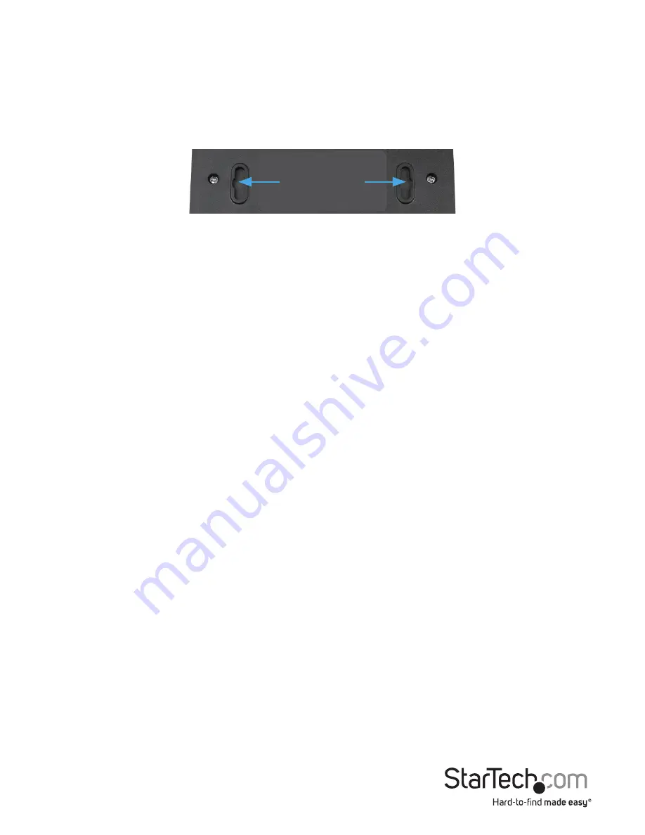
2. The distance between the centers of the two mounting sockets on the back of the
Network Switch are 8.75cm. Mark the distance on the wall, making sure your marks are
straight and level.
3. Depending on the mounting surface, use the appropriate tools and hardware to
install mounting screws into the surface. There should be a gap of approximately 2
mm between the head of the screw and the wall surface.
4. Place the Network Switch so that the wide openings of the mounting sockets are
over the screw heads. Slide the case downward so that the screw heads slide into the
narrow slots.
5. Connect one end of your network cable to an open port on the rear panel of the
Network Switch. Plug the other end of the cable into the RJ-45 port on your network
device (e.g. computer, router, another switch, etc.). Repeat for each additional network
devices you wish to connect to the Network Switch.
6. Plug one end of the power adapter into an open electrical outlet and plug the other
end into the DC connector on the side panel of the Network Switch. The Power LED on
the top of the Switch should now be lit.
7. Once the Switch is powered on, it will be automatically initialized, and all Link/Act
LEDs will flash momentarily, indicating that the system has been reset.
Mounting Sockets


