StarTech.com ARMBARDUO Скачать руководство пользователя страница 17

16

To view manuals, videos, drivers, downloads, technical drawings, and more visit www.startech.com/support

Moving the Plates Up and Down

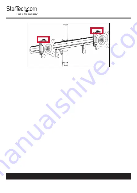
Attaching the Monitors - Flush Installation

Warnings! 

The 

Desk Stand

 is designed to display two moni-

tors between 15 and 24 inches in size. The maximum weight 

capacity of the 

Desk Stand

 is a total of 35.2 lb. (16 kg), with 

each monitor mount able to hold 17.6 lb. (8 kg).
To prevent scratching during the installation process, you 

should handle the surface of the 

Monitors

 with care.

1. 

Insert four of the 

M4x12 mm Screws

 through the 

VESA 

Monitor Mount

 and into the 

Mounting Holes

 on the back 

of the 

Monitor

.

2. 

 Use a 

Phillips Screwdriver

 to tighten the screws.

3. 

Repeat steps 1 - 2 to install the second 

Monitor

.

Содержание ARMBARDUO

Страница 1: ...Manual Revision 04 23 2019 User Manual For the latest information and specifications visit www startech com ARMBARDUO Desk Stand for Dual Monitors Actual product may vary from photos SKU ARMBARDUO...

Страница 2: ...tarTech com Where they occur these references are for illustrative purposes only and do not represent an endorsement of a product or service by StarTech com or an endorsement of the product s to which...

Страница 3: ...eller egendom Denna produkt har st d f r f ljande vikter 16 kg Produkten r endast avsedd f r anv ndning inomhus och ska inte anv ndas utomhus Monteringsutrustningen som medf ljer produkten kanske inte...

Страница 4: ...istruzioni Non superare la capacit di carico del prodotto Il sovraccarico del prodotto potrebbe causare danni o lesioni Il prodotto in grado di supportare i seguenti pesi 16 kg Il prodotto destinato...

Страница 5: ...uido con este producto puede no ser adecuado para algunas estructuras de pared Si no tiene la experiencia suficiente para fijar este producto a la estructura de la pared correspondiente p ngase en con...

Страница 6: ...is les c bles d alimentation et de chargement doivent tre plac s et achemin s de fa on viter tout risque lectrique de chute ou de s curit Misure di sicurezza I cavi inclusi i cavi di alimentazione e d...

Страница 7: ...ct Diagram 7 Front View 7 Product Dimensions 8 Product Information 9 Package Contents 9 Assembly 12 Assembling the Base 12 Attaching the Crossbar 13 Adjusting the Monitor Plates 14 Attaching the Monit...

Страница 8: ...ds technical drawings and more visit www startech com support Product Diagram Front View 1 Crossbar 5 Height Adjustment Ring 2 VESA Monitor Mounts x 2 6 Cable Management Clip 3 Pole 7 Baseplate 4 Cros...

Страница 9: ...8 To view manuals videos drivers downloads technical drawings and more visit www startech com support Product Dimensions...

Страница 10: ...uals videos drivers downloads technical drawings and more visit www startech com support Product Information Package Contents Pole Qty One Baseplate Qty One M6x15 mm Screws Qty Three Cable Management...

Страница 11: ...ideos drivers downloads technical drawings and more visit www startech com support Pole Cap Qty One Height Adjustment Ring Qty One Crossbar Qty One VESA Monitor Mount Qty Two M4x12 mm Screw Qty Eight...

Страница 12: ...11 To view manuals videos drivers downloads technical drawings and more visit www startech com support Plastic Spacers Qty Eight M3 Hex Key Qty One M4 Hex Key Qty One Cable Management Clips Qty Two...

Страница 13: ...ll of the hardware is assembled securely and checked for stability before you install the moni tors Assembling the Base 1 Insert the three M6x15 mm Screws through the three holes in the Baseplate and...

Страница 14: ...the monitors to be at 2 Press the lever on the Height Adjustment Ring to tighten it and prevent it from sliding down the pole 3 Slide the Crossbar down the Pole so that it sits on the Height Adjustmen...

Страница 15: ...s downloads technical drawings and more visit www startech com support Tightening the Crossbar Adjusting the Monitor Plates 1 Loosen the Plates on the Crossbar by turning the Thumb Screws at the botto...

Страница 16: ...es right and left until the Plates are in the desired position Moving the Plates Left and Right 3 When the Plates are in the desired position turn the Thumb Screws at the bottom of the plates clockwis...

Страница 17: ...size The maximum weight capacity of the Desk Stand is a total of 35 2 lb 16 kg with each monitor mount able to hold 17 6 lb 8 kg To prevent scratching during the installation process you should handl...

Страница 18: ...sbar 5 Turn the screw on the side of each of the VESA Monitor Mounts clockwise to tighten the VESA Monitor Mounts in place Attaching the Monitors Recessed Installation 1 Insert four of the M4x30 mm Sc...

Страница 19: ...sit www startech com support Installing the VESA Monitor Mount Recessed Installation 4 Slide each of the VESA Monitor Mounts onto the Plates on the Crossbar 5 Turn the screw on the side of each of the...

Страница 20: ...ownward or upward Place both of your hands on either side of the Monitor and apply light pressure either downward or upward The Monitor will tilt to a maximum of 15 degrees in either direction Monitor...

Страница 21: ...ch the monitors 2 While holding the Plastic Disc located on the front of the VESA Monitor Mount in place tighten the Hex Screw located on the back of the VESA Monitor Mount using a 3 16 Hex Key 3 Once...

Страница 22: ...Cable Management Clips right or left along the Crossbar 2 Run the cable coming from each of the monitors through the corresponding Cable Management Clips crossbar 3 Hold the cables against the Pole a...

Страница 23: ...damages whether direct or indirect special punitive incidental consequential or otherwise loss of profits loss of business or any pecuniary loss arising out of or related to the use of the product exc...

Страница 24: ...tools StarTech com is an ISO 9001 Registered manufacturer of connectivity and technology parts StarTech com was founded in 1985 and has operations in the United States Canada the United Kingdom and Ta...

Отзывы: