background image

– 32 –

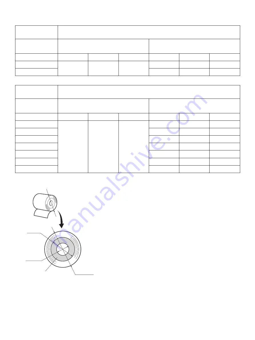
Adjustment value according to the paper you are using

Paper thick-ness 

(μm)

When using the paper roll with a core whose inside diameter (A):ø12, outside diameter 
(B):ø18

Detected diameter (C)

(Approx. mm)

Remained paper length

(Approx. m)

Level 1

Level 2

Level 3

Level 1

Level 2

Level 3

65

ø23

ø27

ø31

2.5

4.9

7.7

75

2.1

4.2

6.7

Paper thick-ness 

(μm)

When using the paper roll with a core whose inside diameter (A): ø25.4, outside di-
ameter (B):ø32

Detected diameter (C)

(Approx. mm)

Remained paper length

(Approx. m)

Level 1

Level 2

Level 3

Level 1

Level 2

Level 3

65

ø36

ø40

ø44

2.8

6.4

10.4

75

2.4

5.5

9.0

85

2.1

4.9

7.9

95

1.9

4.4

7.1

105

1.7

4.0

6.4

130

1.4

3.2

5.2

150

1.2

2.8

4.5

Note: 
1)  The adjuster is factory-set at level 1 on the horizontal 

layout  and  level  3  on  the  vertical/wall-mount  lay-
out.

2)  The control switch or the memory switch A may be 

used to switch between the horizontal and vertical 
(wall-mount) layouts. For instructions on setting the 
memory switch, refer to the separate Specifications 
Manual.

3)  The  detected  diameter  and  remained  paper  length 

given above are calculated values, and there may be 
some variances depending on the rolled state of the 
paper or the actual mechanism.

4)  If thick paper is used (paper thickness between 100 

μm and 150 μm), the paper roll may loosen and cause 
variances in the detected values. Therefore, set the 
adjustor to Level 3 for horizontal layout.

C

C

B

A

Paper roll core

Содержание TSP700II

Страница 1: ...THERMAL PRINTER TSP700II SERIES Hardware Manual...

Страница 2: ...plicables aux appareils num riques de la classe A prescrites dans le R glement sur le brouillage radio lectrique dict par le minist re des Communications du Canada The above statement applies only to...

Страница 3: ...Label Paper Roll Tack Label Paper 23 5 4 AC adapter option 27 6 Control Panel and Other Functions 28 6 1 Control Panel 28 6 2 Errors 28 6 3 Self Printing 30 7 Adjusting the Near end Sensor 31 8 Preve...

Страница 4: ...ons 56 13 4 Electrical Characteristics 56 14 USB Ethernet and Wireless LAN Interface 57 14 1 USB Interface Specifications 57 14 2 Ethernet Interface Specifications 57 14 3 Wireless LAN Interface Speci...

Страница 5: ...onfiguration Fig 1 1 Unpacking If anything is missing contact the dealer where you bought the printer and ask them to supply the missing part Note that it is a good idea to keep the original box and a...

Страница 6: ...l away from heaters and other sources of extreme heat P Make sure that the surrounding area is clean dry and free of dust P Make sure that the printer is connected to a reliable power outlet It should...

Страница 7: ...phone Power connector For connection of the AC adapter Never unplug the AC adapter while the printer is on Printer cover Open this cover to load or replace paper Cover open lever Push this lever in th...

Страница 8: ...le to a parallel port of your PC 3 1 2 RS 232C Interface Cable Connect the RS 232C interface cable to a RS 232C port of your PC 3 1 3 USB Interface Cable Connect the USB interface cable to a USB port...

Страница 9: ...e power cable plug is disconnected from the AC outlet 3 2 1 Parallel Interface Cable 1 Make sure the printer is turn off 2 Affix the ferrite core onto the cable as shown in the illustration 3 Pass the...

Страница 10: ...d off Also make sure the power cable plug is disconnected from the AC outlet 2 Connect the interface cable to the connector on the rear panel of the printer 3 Tighten the connector screws 3 2 3 USB In...

Страница 11: ...off 2 Affix the ferrite core onto the ethernet cable as shown in the illustration below 3 Pass the fastener through the ferrite core 4 Loop the fastener around the cable and lock it Use scissors to cu...

Страница 12: ...supplied CD ROM Drivers and Utilities into the CD ROM drive 3 Follow the instructions that appear on the screen 4 The dialog shown in the illustration indicates that the procedure has been completed...

Страница 13: ...ted from the AC outlet 1 Connect the AC adapter to the power cable Note Use only the standard AC adapter and power cable 2 Connect AC adapter to the connector on the printer 3 Insert the power cable p...

Страница 14: ...t you unplug the printer from the power outlet whenever you do not plan to use it for long periods Because of this you should locate the printer so that the power outlet it is plugged into is nearby a...

Страница 15: ...and that the computer is turned off before making connections 1 Connect the peripheral drive cable to the connector on the rear panel of the printer CAUTION Do not connect a telephone line into the pe...

Страница 16: ...e following condition remove the tension bar unit and change the adjustmentleverpositioninaccordancewith theproceduresdescribedinparagraphs3 7 1 and 3 7 2 Paper thickness between 100 m and 150 m or pa...

Страница 17: ...hermal label paper roll or thermal label paper roll tack label paper Installation layout Horizontal Vertical wall mount Paper width mm 82 5 79 5 57 5 82 5 79 5 57 5 Paper thickness between 65 m and 10...

Страница 18: ...ickness between 105 m and 150 m Position 1 Paper thickness between 65 m and 105 m 3 7 3 Removing the Paper Roll Holder When using a paper roll with an 82 5 mm width remove the paper roll holder as sho...

Страница 19: ...damaged Do not touch them with metal objects sandpaper etc 5 Printing quality may suffer if the thermal head heating element becomes soiled by being touched with your hands Do not touch the thermal he...

Страница 20: ...ced horizontally the use of the partial cut is recommended If you use the full cut the cut pieces of paper may fall into the paper outlet passage causing a paper jam as a result of cutting multiple pi...

Страница 21: ...4 1 Attaching the Holder Plate 1 Attach the shaft to the printer 2 Wipe the area into which the rubber feet will be affixed in order to remove any grime then affix the roll stoppers The positions for...

Страница 22: ...lide it downward to set it in place CAUTION The weight of the printer including a roll of paper with the largest diameter is approximately 2 4 kg The screws installed in the wall must have both a shea...

Страница 23: ...s necessary for you By install ing the switch blind the following become possible Preventing the power switch from being operated by mistake Ensuring that other people can not easily operate the power...

Страница 24: ...r inner diameter Paper thickness Core outer Core inner 65 75 m 18 1 mm 12 1 mm 65 75 m 32 1 mm 25 4 mm 75 150 m 32 1 mm 25 4 mm Printed surface Outer edge of roll Tail end handling Do not use paste or...

Страница 25: ...ss To change the darkness settings use the printing dark ness settings command ESC RS d n Refer to the separate programmer s manual for details 2 The print density may vary depending on the type of pa...

Страница 26: ...parator Total thickness Lintec LD2114 For distribution or information control 65 41 115 High adhesion Lintec LD5530 For measurement 85 65 150 High adhesion Ricoh 130LHB For distribution or information...

Страница 27: ...Label Paper Roll Tack Label Paper 1 Label paper specification Backing paper width 79 5 0 5 mm or 82 5 0 5 mm Outer roll diameter 100 mm or less Take up paper roll width 80 0 5 1 mm or 83 0 5 1 mm Thi...

Страница 28: ...change the settings for printing darkness To change the darkness settings use the printing dark ness settings command ESC RS d n Refer to the separate programmer s manual for details 2 The print dens...

Страница 29: ...r backing paper Base material label paper Printing direction Black mark back of diagram Details of recommended tack label specifications for 79 5 mm backing paper PCS 0 90 minimum 83 0 5 1 0 Rolled di...

Страница 30: ...with font A Dot numbers 39 622 Minimum settable top margin when paper is fed using back feed Effective printing range 1 75 1 75 0 5 3 Bottom margin 1 75 79 5 mm backing paper 1 75 0 5 4 5 Top margin 3...

Страница 31: ...ship Cut position Printing line Black mark sensor Approx 13 Approx 14 5 4 AC adapter option AC adapter which are not specified may result in damage to the printer fire or electric shock Model name PS6...

Страница 32: ...ON ON Orange Automatically recovered by loading a new paper roll then closing the printer cover Paper near end ON Flashes orange lamp at 1 second intervals Indicators show that the paper end is appro...

Страница 33: ...range lamp at 1 sec ond intervals This is not a recoverable error Head thermistor error OFF Flashes Red lamp at 1 5 sec ond intervals This is not a recoverable error Power voltage error OFF Flashes Or...

Страница 34: ...power on while holding the FEED button When the cover is closed HEX DUMP PRINTING is printed and the printer enters the Hexadecimal Dump Mode Each of the signals sent from the computer to the printer...

Страница 35: ...over 2 Determine the diameter of the paper roll you are using and find the required setting in the table below 3 Insert the tip of a ballpoint pen or similar object into the hole of the adjuster and t...

Страница 36: ...9 4 4 7 1 105 1 7 4 0 6 4 130 1 4 3 2 5 2 150 1 2 2 8 4 5 Note 1 The adjuster is factory set at level 1 on the horizontal layout and level 3 on the vertical wall mount lay out 2 The control switch or...

Страница 37: ...paper roll straight and close the printer cover gently Note 1 Make sure that the paper is positioned straight If the printer cover is closed with the paper skewed a paper jam may result Note 2 Lock t...

Страница 38: ...of the glue that may have accumulated Note 1 The thermal head is easily damaged so clean it with a soft cloth taking care not to scratch it Note 2 Do not attempt to clean the thermal head immediately...

Страница 39: ...03 dpi 8 dots mm 0 125 mm dot 4 Printing width Max 80 mm 5 Number of print columns 53 12 24 dots 6 Paper roll Refer to chapter 4 for details on the recommended paper roll Paper width 79 5 0 5 or 82 5...

Страница 40: ...0 print duty Approx peak 11 9 A Solid printing Approx average 5 0 A Continuous solid printing should be 10 seconds or less 3 Power Connector Pin No Function 1 Drive power 24 V 2 Signal GND 3 N C Shell...

Страница 41: ...without condensation 2 Transport storage except for paper Temperature 20 C to 60 C Humidity 10 to 90 RH without condensation RH 34 C90 RH 40 C65 RH 45 C50 RH 90 80 60 40 20 10 0 10 20 30 40 50 Tempera...

Страница 42: ...er width 57 5 mm Paper thickness between 65 m and 85 m 600 000 partial cuts 500 000 full cuts Paper width 82 5 mm 79 5 mm full face thermal label paper Paper thickness between 100 m and 150 m 300 000...

Страница 43: ...regards to the top margin approximately 13 mm is established between the print position and the cut position auto cutter and the paper is fed through 1 mm or more eight dot lines if printing is perfor...

Страница 44: ...e settings will become effective when the power switch is set to on again The following is the procedure for changing the settings on DIP switches 1 Make sure the printer is turned off 2 Remove the sc...

Страница 45: ...buffer full Receive buffer full 1 7 Automatic status back function Invalid Valid 1 8 Should not be changed Should be set to on 1 9 Low power consumption mode Invalid Valid 1 10 Should not be changed S...

Страница 46: ...42 DIP SW 2 Switch Function ON OFF 2 1 Always ON Should be set to on 2 2 2 3 2 4 The factory settings of DIP switch are all on...

Страница 47: ...buffer full Receive buffer full 1 7 Automatic status back function Invalid Valid 1 8 Should not be changed Should be set to on 1 9 Low power consumption mode Invalid Valid 1 10 Should not be changed S...

Страница 48: ...44 DIP SW 2 Switch Function ON OFF 2 1 Always ON Should be set to on 2 2 2 3 2 4 The factory settings of DIP switch are all on...

Страница 49: ...rews 6 Turn on the printer and all components connected to it The factory settings of DIP switch are all on except for switches 7 and 8 DIP SW 3 Switch Function ON OFF 3 1 Baud Rate See table below 3...

Страница 50: ...ine or receive buffer full Receive buffer full 1 7 Automatic status back function 1 Invalid Valid 1 8 Should not be changed Should be set to on 1 9 Low power consumption mode Invalid Valid 1 10 Should...

Страница 51: ...n 1 6 Handshaking conditions conditions for BUSY Offline or receive buffer full Receive buffer full 1 7 Should not be changed Should be set to on 1 8 Should not be changed Should be set to on 1 9 Low...

Страница 52: ...on is recognized as 100BASE TX Red Lights when packets are received Push Switch LED 11 5 Wireless LAN Interface Model ON ON OFF OFF DIP SW 1 Switch Function ON OFF 1 1 Command emulation Ster Line mode...

Страница 53: ...e all on DIP Switch ON OFF 3 1 Fixed at OFF 3 2 Initialize of setting information Change DIP Switch 3 2 to ON initialize the setting information when the power is turned on The factory settings of DIP...

Страница 54: ...y observe the export control laws of the country for export when exporting this product Installing the Ferrite Core Wireless LAN Model for EU Only Install the ferrite core onto the peripheral drive ca...

Страница 55: ...51 Connecting the peripheral drive cable Connect the peripheral drive cable to the connector on the printer Then connect the other end of the cable to the peripheral drive circuit Except for EU For EU...

Страница 56: ...1 4 In Out Data2 Data2 5 In Out Data3 Data3 6 In Out Data4 Data4 7 In Out Data5 Data5 8 In Out Data6 Data6 9 In Out Data7 Data7 10 Out nAck PtrClk 11 Out Busy PtrBusy Data3 7 12 Out PError AckDataReq...

Страница 57: ...ion method Asynchronous serial interface 2 Baud rate Selectable from 4800 9600 19200 38400 bps Refer to 11 DIP Switch Setting 3 Word length Start bit 1 bit Data bit 7 or 8 bits selectable Parity bit O...

Страница 58: ...abled except when transmitting data by DLE EOT and GS a B X ON X OFF communication mode Status of this signal is not checked When DIP Switch 3 7 ON This is an externally reset signal A space above 1 m...

Страница 59: ...he self printing BUSY BUSY 3 When the cover is open BUSY 4 During the paper feeding by FEED button BUSY 5 When the printer stops printing due to a paper end BUSY 6 During macro executing standby statu...

Страница 60: ...less than 3 m in length 13 4 Electrical Characteristics Voltage Data signal Control signal Binary status 3 V to 15 V Mark OFF 1 3 V to 15 V Space ON 0 1 2 3 4 5 6 1 2 3 4 5 6 7 8 20 FG FG TXD RXD RTS...

Страница 61: ...fication Conforms to IEEE802 3 2 Communication Media 10 Base T 100 Base TX 3 Communication Speed 10 100 Mbps 4 Protocol TCP IP 5 TCP IP detail ARP RARP BOOTP DHCP LPR 9100 FTP HTTP TELNET TFTP 6 Conne...

Страница 62: ...connect it to a telephone Use cables which meet the following specifications Peripheral Drive Connector Drive circuit The recommended drive unit is shown below Wire lead Modular plug MOLEX 90075 0007...

Страница 63: ...wing ON time ON time OFF time 0 2 4 Minimum resistance for coils L1 and L2 is 24 5 Absolute maximum ratings for diodes D1 and D2 Ta 25 C are Average Rectified Current Io 1 A 6 Absolute maximum rating...

Страница 64: ...emory switches see the separate Specification Manual The table below shows the factory settings for the memory switches Memory Switch Hexadecimal Code 0 0000 1 0000 2 0000 3 0000 4 0000 5 0000 6 0000...

Страница 65: ...tion layout Horizontal Paper width mm 82 5 79 5 Paper thickness between 100 m and 150 m Neces sary Neces sary Paper thickness between 65 m and 100 m Unnec essary Unnec essary Correct Installation layo...

Страница 66: ...se access the following URL http www star m jp eng dl dl02 htm for the latest revision of the manual OVERSEAS SUBSIDIARY COMPANIES STAR MICRONICS AMERICA INC 1150 King Georges Post Road Edison NJ 0883...

Отзывы: