background image

- 8 -


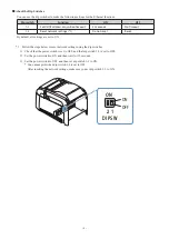
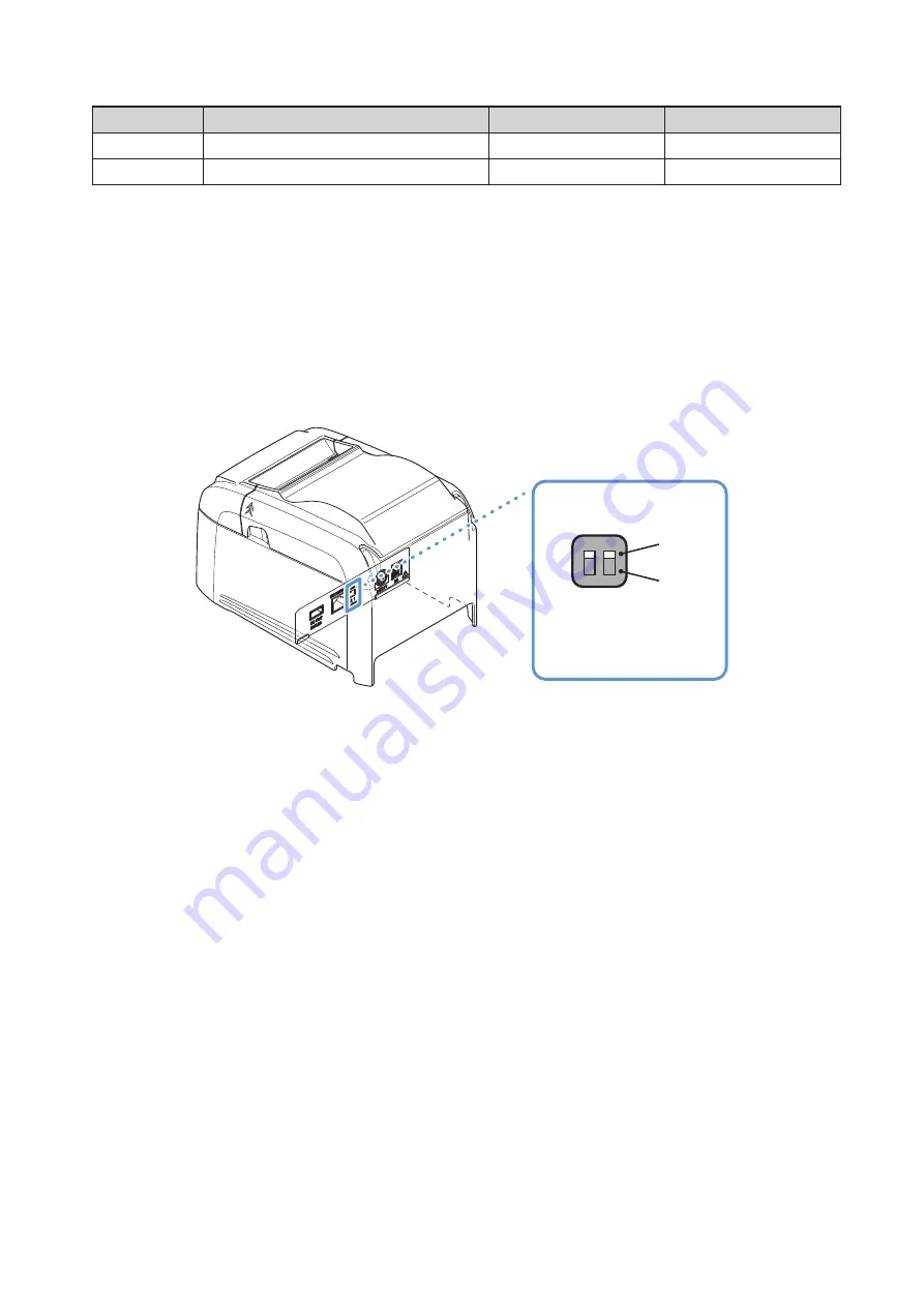
About the Dip Switches

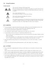
You can use the dip switches to make the following settings for the Ethernet functions.

Dip switch

Function

ON

OFF

1-1

Set DHCP address acquisition timeout

20 seconds

No Timeout

1-2

Reset network settings (*1)

Do not reset

Reset

By default, all settings are set to ON.

*1  Follow the steps below to reset network settings using the dip switches.

1)  Check that the power switch is set to OFF, and that dip switch 1-2 is set to OFF.
2)  Set the power switch to ON, and then wait for 15 seconds.
3)  Set the power switch to OFF, and then set dip switch 1-2 to ON.

*  You cannot print when dip switch 1-2 is set to OFF. 

After resetting the network settings, make sure you set dip switch 1-2 to ON.

ON

ON
OFF

DIPSW

2 1

Содержание TSP043E Series

Страница 1: ...Hardware Manual THERMAL PRINTER TSP043 Series ...

Страница 2: ...s device must accept any interference received including interference that may cause undesired operation FCC CAUTION Changes or modifications not expressly approved by the party responsible for compliance could void the user s authority to operate the equipment NOTE This equipment has been tested and found to comply with the limits for a Class A digital device pursuant to part 15 of the FCC Rules ...

Страница 3: ...ch it This symbol is located near the cutter Never touch the cutter blade as you could injure your fingers This symbol is located near the peripheral drive connector Do not connect this to a telephone This symbol is located near the screws securing the case or the protective plate which should not be opened by individuals other than service personnel Individuals other than service personnel should...

Страница 4: ...e AC Adapter 9 3 4 Turning the Power On 10 3 5 Connecting to a Peripheral Device 10 3 6 Loading a Paper Roll 11 3 7 Changing the Paper Width 13 3 8 Setup Precautions 14 4 LED Display 16 4 1 Error Indicators 16 5 Preventing and Removing Paper Jams 17 5 1 Preventing Paper Jams 17 5 2 Removing Paper Jams 17 5 3 Releasing the Cutter Lock 18 6 Maintenance 19 6 1 Thermal Head 19 6 2 Platen Rubber Roller...

Страница 5: ...sure that the surrounding area is clean dry and free of dust 7 Make sure that the printer is connected to a reliable power outlet It should not be on the same electric circuit as copiers refrigerators or other appliances that cause power spikes 8 Make sure that the room where you are using the printer is not too humid 9 Use the printer within the boundaries indicated in the environmental requireme...

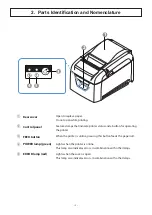
Страница 6: ...tus and a button for operating the printer 3 FEED button When the printer is online pressing this button feeds the paper roll 4 POWER lamp green Lights when the printer is online This lamp also indicates errors in combination with other lamps 5 ERROR lamp red Lights when the cover is open This lamp also indicates errors in combination with other lamps 1 5 4 2 3 ...

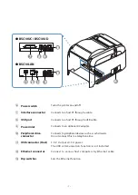
Страница 7: ...rt Connects to a host PC through a USB cable 9 Power inlet Connects to an optional AC adapter 0 Peripheral drive connector Connects to peripheral devices such as cash drawers Do not connect this to a telephone line A USB connector Host 5 0 V Outputs 0 5 A power The USB communication function is not installed B Ethernet connector Connect to various host computers by Ethernet cable C Dip switches Se...

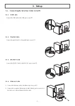
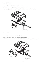
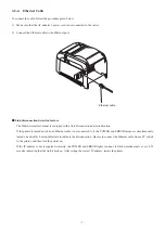
Страница 8: ... Connect the parallel cable to the parallel port on your PC 3 1 3 RS 232C Cable Connect the RS 232C cable to the RS 232C port on your PC 3 1 4 Ethernet Cable 1 Connect the Ethernet cable to the Ethernet port on your PC 2 Connect the computer s Ethernet port to the Ethernet port on a router or a hub and so on with an Ethernet interface cable ...

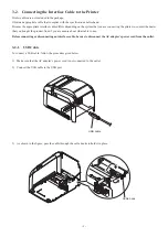
Страница 9: ...the dealer that you bought the product from if you are unsure about what cable to use Before connecting or disconnecting an interface cable be sure to disconnect theAC adapter s power cord from the outlet 3 2 1 USB Cable To connect a USB cable follow the procedure given below 1 Make sure that the AC adapter s power cord is not connected to the outlet 2 Connect the USB cable to the USB port 3 As sh...

Страница 10: ...ble to the connector on the RS 232C interface board and tighten the left and right screws 3 2 2 Parallel Cable To connect a parallel cable follow the procedure given below 1 Make sure that the AC adapter s power cord is not connected to the outlet 2 Connect the parallel cable to the connector on the parallel interface board and fasten the connector clasps RS 232C cable Parallel cable ...

Страница 11: ...ure If the printer is turned on when an Ethernet cable is not connected to it the POWER and ERROR lamps are simultaneously turned on and off at 4 second intervals to indicate the disconnection Be sure to connect the Ethernet cable from a PC or hub to the printer and then turn the printer on If the IP address is not recognized correctly the POWER and ERROR lights continue to flash simultaneously ev...

Страница 12: ...fault all settings are set to ON 1 Follow the steps below to reset network settings using the dip switches 1 Check that the power switch is set to OFF and that dip switch 1 2 is set to OFF 2 Set the power switch to ON and then wait for 15 seconds 3 Set the power switch to OFF and then set dip switch 1 2 to ON You cannot print when dip switch 1 2 is set to OFF After resetting the network settings m...

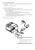
Страница 13: ...that is 24 VDC 10 and 2 1 A or more Select a power supply with current capacity that is appropriate for the actual printing ratio Use a power supply that supports with SELV output Take into consideration the noise in the environment that the printer is installed in and take appropriate measures to protect the printer from static electricity AC line noise etc 2 Connect the AC adapter to the connect...

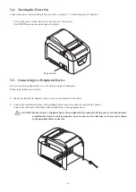
Страница 14: ...plug Follow the procedure given below 1 Make sure that the AC adapter s power cord is not connected to the outlet 2 Connect the modular jack plug to the peripheral drive connector on the rear panel of the printer Connect the other end of the cable to the modular jack of the peripheral device CAUTION Do not connect a telephone line to the peripheral drive connector Doing so may cause the printer to...

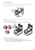
Страница 15: ...o get your fingers caught when opening or closing the printer s rear cover 3 After the rear cover is closed the printer performs initial operations from paper feeding to paper cutting Do not open the rear cover until the initial operations are complete 2 Load the paper roll into the printer in the direction indicated by the figure and pull the leading edge of the paper straight toward you Note 1 P...

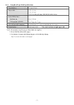
Страница 16: ... mm Take up paper roll width 80 0 5 mm 58 0 5 mm Core inner and outer diameters Inner diameter 12 1 mm external diameter 18 1 mm Printed surface Outer edge of roll You cannot use inner wrapped paper rolls Note 1 Do not glue or tape the paper roll and shaft core together 2 Do not fold the tail end of the paper 3 For details on recommended thermal paper see the following webpage http www starmicroni...

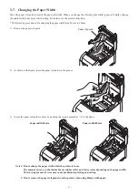
Страница 17: ...roll guide 2 As shown in the figure insert the paper roll guide in the groove 3 Secure the paper roll guide in place by pushing the section marked as A in the figure Note 1 Do not change the paper width while the printer is in use The amount of wear on the thermal head rubber roller and cutter varies depending on the paper width This varying amount of wear may cause problems in printing and cuttin...

Страница 18: ... the tear bar There is a cutter or tear bar inside the paper outlet slot Never put your hand in the slot regardless of whether or not the printer is in operation You must open the printer cover to replace paper However because the cutter blade or tear bar is located inside of the cover be careful not to bring your face and hands too close to the blade or tear bar when the cover is open During and ...

Страница 19: ... heating element Doing so may make it dirty which will decrease the printing quality Static electricity can damage the driver IC and other components of the thermal print head Avoid touching it directly Do not operate the printer if there is moisture which has been caused by condensation or another factor on the front sur face of the head The printing quality and the thermal print head s service l...

Страница 20: ...verable errors Turn the printer off check the recovery conditions and then turn the printer back on If the same error occurs after you turn the printer back on the printer needs to be repaired Error description POWER ERROR Cause Recovery condition Cutter error Off Flashes at 0 25 second intervals Paper cutting in progress error After you restart the printer the printer recovers when the mobile cut...

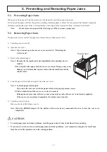
Страница 21: ... Do not pull on the paper with the rear cover closed Doing so may cause damage to or deformation of parts such as the thermal head and the rubber roller 4 Load the paper roll straight and gently close the rear cover Note 1 Load the paper roll straight If you close the rear cover with the paper roll skewed paper jams may occur 2 Push on both sides of the rear cover to close it securely Pushing the ...

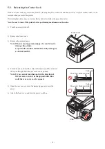
Страница 22: ...he jammed paper Note When removing jammed paper be careful not to damage the printer In particular the thermal head is easily damaged so do not touch it 4 Turn the knob in front of the cutter in the direction of the red arrow shown on the right until the rear cover can be opened Note If you can not turn the knob in the direction of the red arrow turn it in the opposite direction until the rear cov...

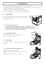
Страница 23: ...oft cloth wipe off the dirt from the rubber roller Clean the entire rubber roller by rotating it 6 3 Paper Holder Clean the paper holder of debris dust paper particles etc that may have accumulated Note 1 The thermal head is easily damaged Be sure to clean the thermal head with a soft cloth and be careful not to damage the head 2 Do not clean the thermal head immediately after printing when the th...

Страница 24: ...http www starmicronics com support Rev 2 1 ...

Отзывы: