– 8 –
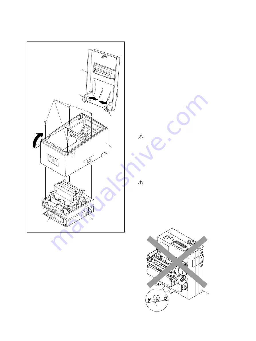
1.
Case Unit
(1)
Turn off the power switch
1
, disconnect the power
cord from the wall outlet.
(2)
Lift up the front of printer cover
2
and open printer
cover.
(3)
Spread to the outside at points A (left / right) of printer
cover
2
and remove printer cover.
(4)
Remove
•
Four screws
3
•
Case unit
4
Lift the case unit
4
.
At this time, avoid the power switch
1
.
Caution 1:
When removing the case unit
4
, rotate it while pulling
it toward so that it does not hit the FEED switch
5
.
It is possible to damage the FEED switch if a strong
force is applied to it.
When remounting the case unit, be careful not to hit the
FEED switch
5
.
Caution 2:
After removing or before remounting the case unit,
absolutely never set the mechanical unit
6
with the
FEED switch facing downward.
The FEED switch can be pulled from the frame cause
a strong force to be applied to it which can result in its
becoming damaged.
ER
RO
R
ER
RO
R
PO
W
ER
PO
W
ER
FE
ED
FE
ED
1
5
3
2
4
A
A
6
5
Содержание SP500 Series
Страница 1: ...DOT MATRIX PRINTER SP500 Series TECHNICAL MANUAL FOURTH EDITION ...
Страница 24: ... 21 Fig 3 2 Lubricated Areas B C D E A A F G F G B C D E 1 7 6 8 0 A D A 2 3 9 5 4 B C C ...
Страница 25: ... 22 Fig 3 3 Screw Locking a b c d e e ...
Страница 42: ... 39 Main Logic Board Parallel Interface 3 4 ...
Страница 43: ... 40 Main Logic Board Parallel Interface 4 4 ...
Страница 44: ... 41 5 2 Component Layout ...
Страница 51: ... 48 Main Logic Board RS 232C Interface 3 4 ...
Страница 52: ... 49 Main Logic Board RS 232C Interface 4 4 ...
Страница 53: ... 50 6 2 Component Layout ...
Страница 60: ... 57 Main Logic Board USB Ethernet Wireless LAN Interface 3 4 ...
Страница 61: ... 58 Main Logic Board USB Ethernet Wireless LAN Interface 4 4 ...
Страница 62: ... 59 UPC358 7 2 Component Layout ...
Страница 67: ... 64 8 Power Supply Unit 8 1 Circuit Diagram ...
Страница 68: ... 65 8 2 Component Layout ...
Страница 71: ... 68 9 USB Interface Board 9 1 Circuit Diagram ...


