


8 | TA54 User Manual
What is TA54 Hydraulic Tamper?
TA54 is a hand held hydraulic tool used to compact soil around utility poles,
signs and fence posts. TA54 requires an external hydraulic power supply
capable of supplying 3-9 GPM @ 1000-2000 PSI.
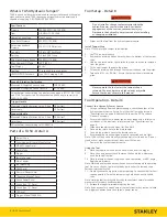
Specifications
Pressure
1000-2000 PSI (69-138 BAR)
Flow
3-9 GPM (11-34 LPM)
Hydraulic Circuit Type
Open Center
Max. Relief Pressure
2250 PSI (155 BAR)
Recommended Back
Pressure
250 PSI (17 BAR) or less
Couplers
3/8 Inch NPT Flush Face
Port Size
1/2 Inch SAE O-ring
Min. Hose Pressure Rating
2500 PSI (172 BAR)
Max. Hydraulic Oil Temp.
140°F (60°C)
Tool Weight
25 Lbs.
Tool Size
71 Inches x 4 Inches x 4 Inches
HTMA/EHTMA Category
Type I & II, Category C & D
Sound & Vibration Declaration
Measured A-Weighted sound power
108.38 dBA
Measured A-Weighted Sound Pressure
97.39 dBA
Values determined according to noise test code given in ISO 15744, 11203
and 3744. Test conducted by independent notified body to comply with
2000/14/EC:2006.
Trigger Handle
Measured Vibration Emission Value: 3-Axis
58.9 m/sec²
Uncertainty
13.2 m/sec²
Support Handle
Measured Vibration Emission Value: 3-Axis
59.6 m/sec²
Uncertainty
13.2 m/sec²
Values determined according to ISO 28927-6
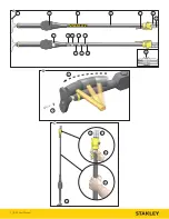
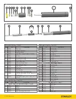
Parts of a TA54 - Detail A
1
Tamper Shoe
2
Serial Number & Year of Manufacture
3
STANLEY Logo Decal
4
Handle Tube
5
Trigger
6
Female Coupler
7
Male Coupler
8
Tool Name Tag
9
GPM Decal
10
Electrical Danger Decal
11
“Read the Manual” Decal
12
Sound Power Decal
13
Circuit Type “D” Decal
14
Circuit Type “C” Decal
15
CE Decal
16
Trigger - Model TA54603A
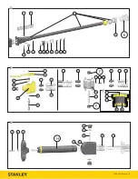
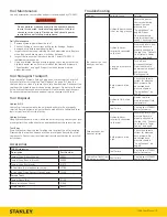
Tool Setup - Detail B
Do not install or change tool accessories while the
hydraulic power source is connected. Accidental
engagement of the tool can cause serious injury.
Disconnect the hydraulic power source before installing
or changing accessories.
1. Disconnect the tool from the hydraulic power source.
Install Tamper Shoe
Note: TT54 ships with a tamper shoe installed.
2. Lay TT54 on a workbench.
3. Remove the retaining bolt and washer from the bottom of the tamper
shoe.
4. Using a soft faced mallet, lightly strike the top of the shoe to remove it
from the piston.
5. Fit the new tamper shoe onto the piston.
6. Thread the retaining bolt through the tamper shoe and into the piston.
7. Torque to 41 Ft. Lbs. (54 Nm). Ensure the tamper shoe is locked into
place.
Never operate the tool unless the tamper shoe is
retained. Shoe can become a high velocity projectile.
Secure the shoe as shown in this manual.
Tool Operation - Detail C
Connect to a Hydraulic Power Source
1. Using a calibrated flow and pressure gauge, check the output of the
hydraulic power source. Ensure it matches the flow and pressure in
“Specifications” on page 8. Hydraulic fluid must be 50°F or above.
Preheat if necessary.
2. Ensure that the hydraulic power source is equipped with a relief valve
set to open at the maximum relief pressure. See “Specifications” on
page 8.
3. Wipe hose couplers with a clean, lint free cloth.
4. Connect the return hose to the male coupler.
5. Connect the pressure hose to the female coupler.
6. Ensure couplers are undamaged, properly connected and are tight.
Note: TA54 will rise quickly when hydraulic power is first turned on. Do not
stand over, or place any part of your body, over the tamper.
7. Power up the hydraulic power source.
Using the Tool
8. Place your dominant hand on the handle tube, over the trigger.
9. Place you non-dominant hand lower on the handle tube, where you
can best control the tool.
10. Place the tamper shoe on the ground to be compacted, at a 90° angle.
Apply down pressure.
Note: Maintain a balanced body position and secure footing while operating
tool. Do not put hands, feet or other body parts under the tamping shoe.
Personal injury could result.
11. Slowly squeeze the trigger to start compacting. Squeeze harder for fast
speed operation. Guide the tamper using both hands on the handle
tube.
Note: Hold the tool correctly and be ready to counteract normal or sudden
movements. Have both hands available.
12. Release the trigger to immediately stop the tool.
Note: If you encounter a breakdown or the tool stops for any reason, release
the trigger and power down the hydraulic power source.
Содержание TA54
Страница 2: ...2 TA54 User Manual 1 2 3 5 6 7 8 9 10 11 12 13 14 15 16 4 A B 3 4 C 4 5 8 10 9...
Страница 10: ......
Страница 11: ......


